This text hasn’t been in the blog in 2006, I took it from my old CMS in 2015.
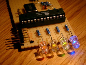
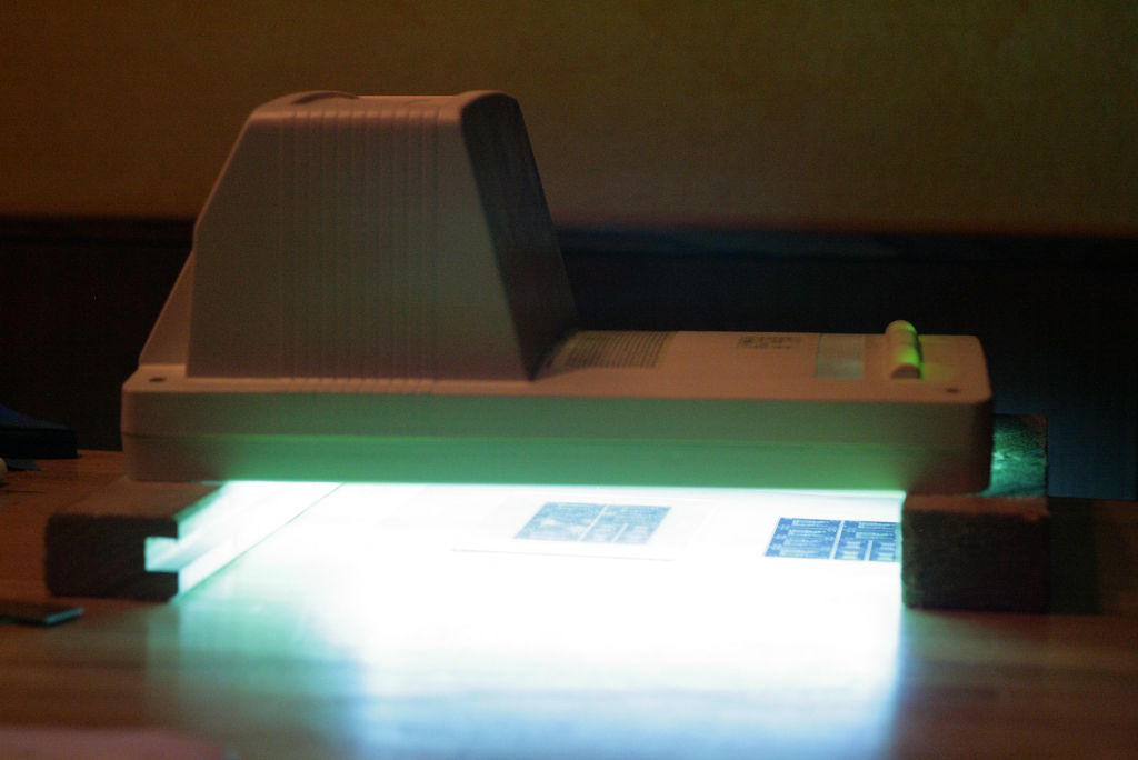
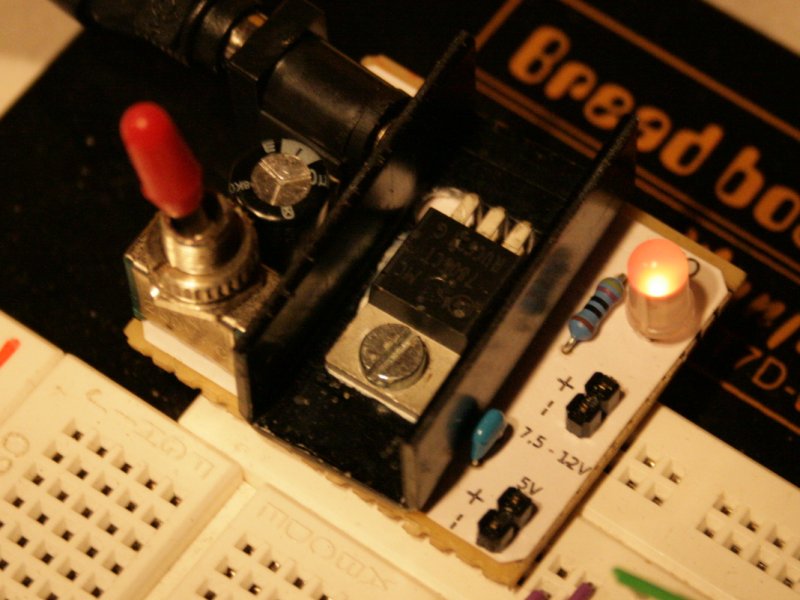
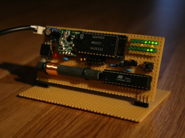
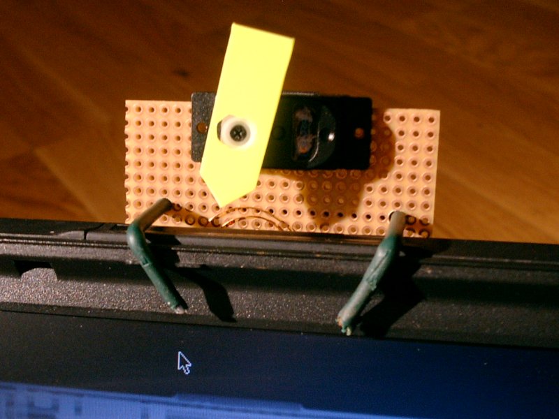
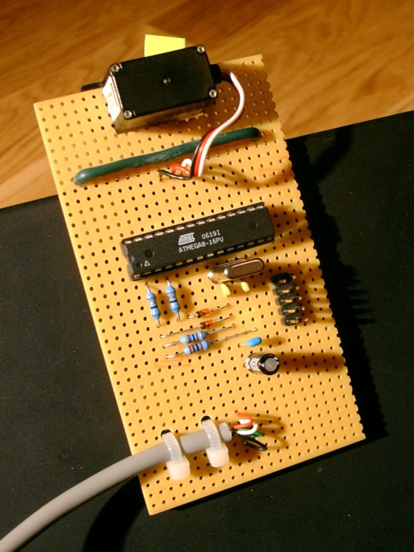
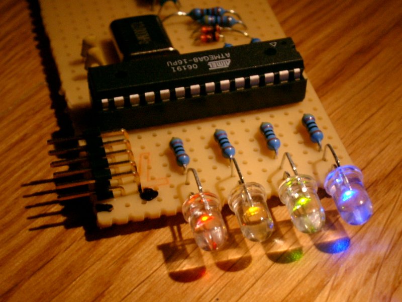
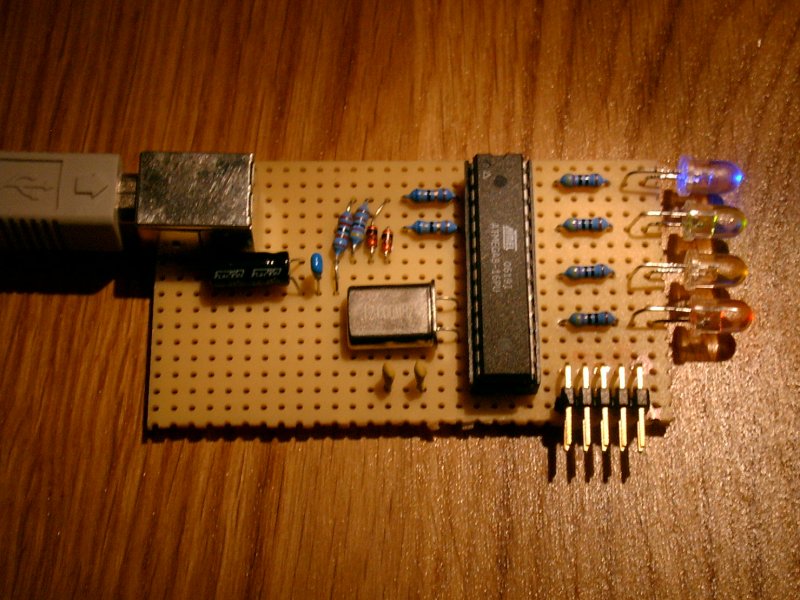
The device in action.
The USB-LED-Fader is a device to control a number of LEDs via USB. I built it to display the online status of my internet connection, the recording status of my video recorder (VDR), and warnings if the available disk-space is low. You can imagine an endless number of applications for this.
The LEDs are controlled with pulse width modulation (PWM). That way, they are not only on or off, it is possible to control the brightness. Included in the device are a number of ‘waveforms’ that can be displayed through the LEDs. That way, one LED can display some kind of a sine- or triangular wave without any interaction with the controlling host.
Every LED can be controlled individually; each one can display its own waveforms.
You can assign three different waves to every LED. The first two (0 & 1) are ‘eternal’ waves. They are displayed alternating until anything different is required. The third wave (2) is only displayed once; afterwards the device will switch back to alternating between the first two waves.
They are displayed alternating until anything different is required. The third wave (2) is only displayed once, afterwards the device will switch back to alternating between the first two waves.
One wave is described by three parameters: the waveform, the duration for one repetition of the wave and the number of repetitions before switching to the next wave.
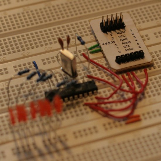
This version supports four LEDs. It should be quite easy to change that number to between one and eight. I have not tested any number greater than four, but I can imagine that the load on the controller may be too high to reliably communicate via USB.
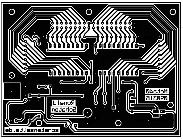
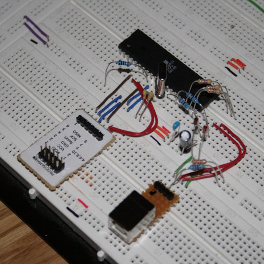
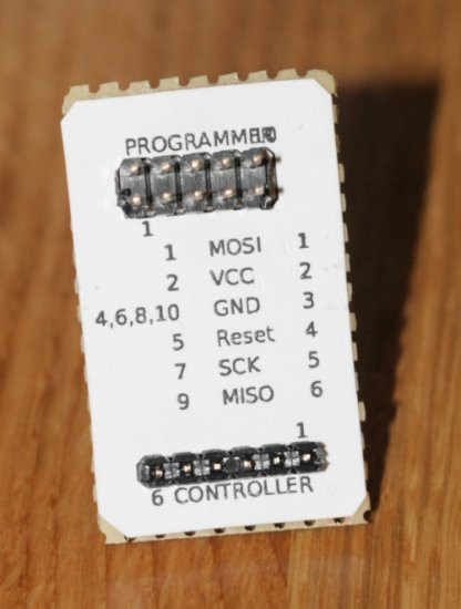
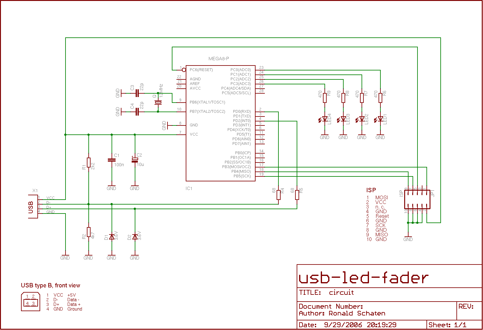
There are three parts included in the distribution: The firmware for an ATmega8 microcontroller, a command line client that can be run under Linux, and the circuits needed to build the device.
This project is based on the PowerSwitch example application by Objective Development. Like that, it uses Objective Development’s firmware-only USB driver for Atmel’s AVR microcontrollers.
Objective Development’s USB driver is a firmware-only implementation of the USB 1.1 standard (low speed device) on cheap single chip microcomputers of Atmel’s AVR series, such as the ATtiny2313 or even some of the small 8-pin devices. It implements the standard to the point where useful applications can be implemented. See the file “firmware/usbdrv/usbdrv.h” for features and limitations.
Building and installing
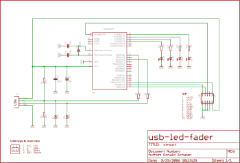
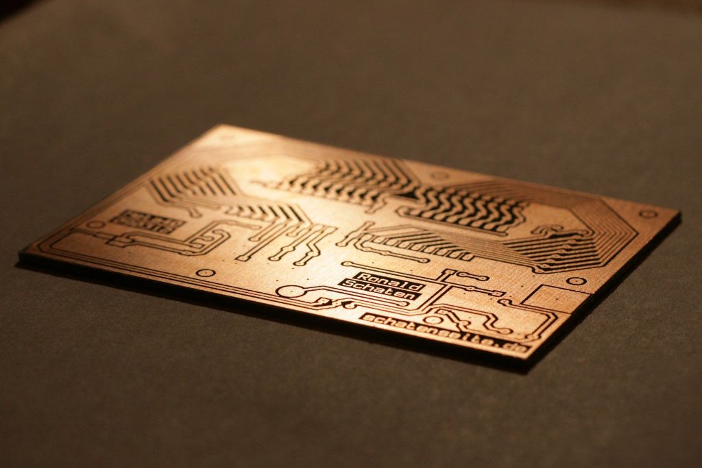
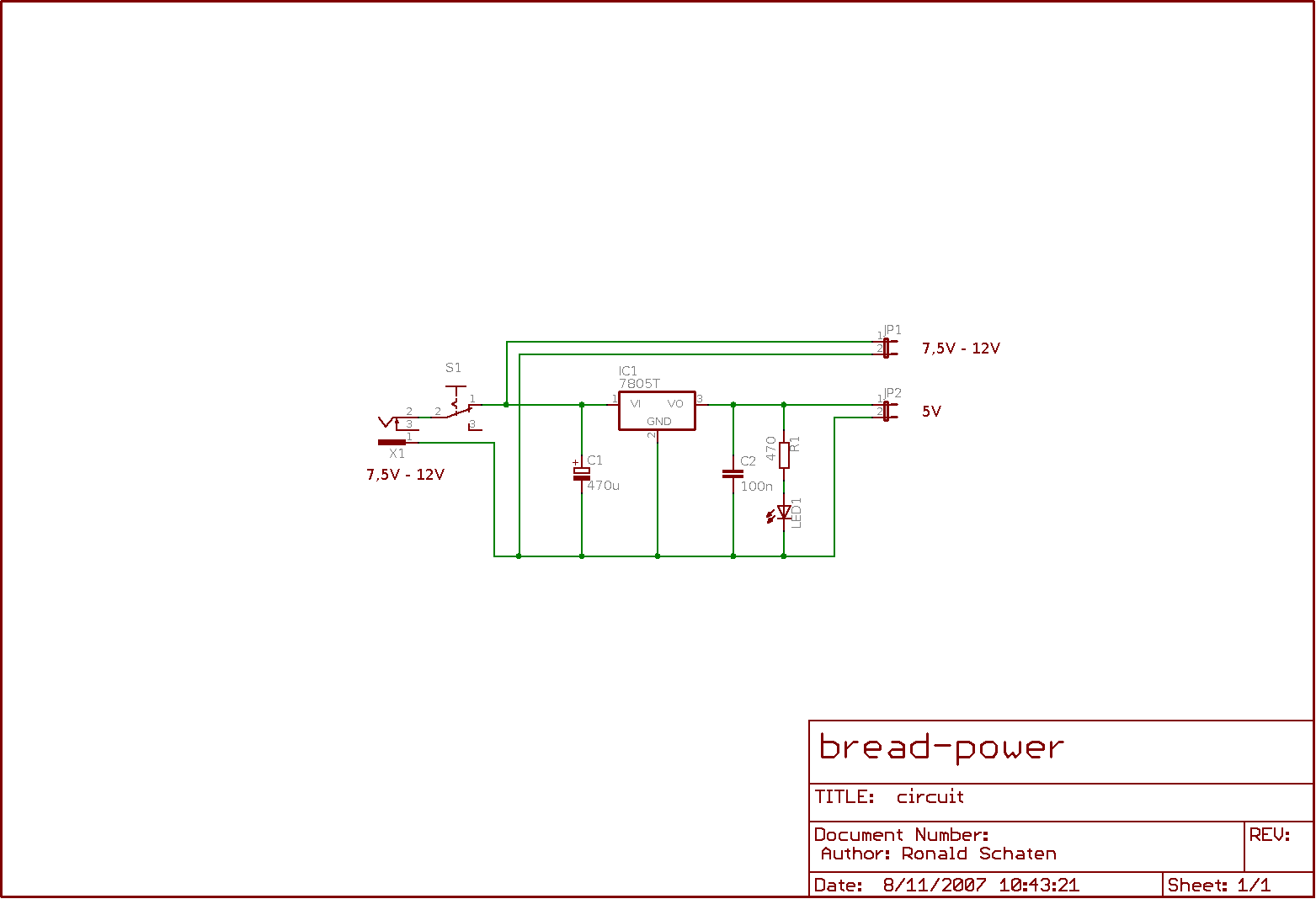
The circuit contains only a few standard components. There’s no special USB-chip involved.
The installation is described in the documentation.
Usage
Connect the device to the USB port. All LEDs should flash up to indicate that the device is initialized.
Then use the command line client as follows:
|
|
usb-led-fader status usb-led-fader set <ledid> <waveid> <waveformid> <periodduration> <repetitioncount> usb-led-fader clear <ledid> usb-led-fader reset usb-led-fader show <waveformid> usb-led-fader test |
When using the set function, it is possible to define several waves at once. You simply have to give the parameters for all waves. See examples below.
Parameters
- ledId: ID of the LED (0-n, depending on the number of LEDs in your circuit).
- waveId: ID of the wave (0-1: constant waves, 2: override).
- waveformId: ID of the waveform (0-31: brightness, 32-37: patterns). For a reference to the patterns, use the show function.
- periodDuration: Time in sec/10 for one repetition of the waveform. A value of 0 can be used to reset the wave.
- repetitionCount: Number of repetitions before switching to the next wave. A value of 0 can be used to repeat this forever.
Examples
Get the status of all LEDs
This will result in output similar to this:
1 2 3 4 5 6 7 8 9 10 11 12 13 14 15 16 17 18 19 20 21 22 23 24 |
LED 0 curid curvalue curpos currep nextupd 0 2 26 0 23 wave waveform length repeat duration updtime 0 38 32 1 20 45 1 0 1 1 0 1 2 0 1 1 0 1 LED 1 curid curvalue curpos currep nextupd 0 14 19 0 19 wave waveform length repeat duration updtime 0 38 32 1 20 45 1 0 1 1 0 1 2 0 1 1 0 1 LED 2 curid curvalue curpos currep nextupd 0 31 16 0 43 wave waveform length repeat duration updtime 0 38 32 1 20 45 1 0 1 1 0 1 2 0 1 1 0 1 LED 3 curid curvalue curpos currep nextupd 0 6 9 0 39 wave waveform length repeat duration updtime 0 38 32 1 20 45 1 0 1 1 0 1 2 0 1 1 0 1 |
In this output, the values curvalue, curpos, nextupd and updtime are for debugging purposes only. They shouldn’t be of interest to the common user. The meaning of the other values should be clear.
Set the first LED to keep a moderate brightness
|
|
usb-led-fader set 0 0 15 10 1 |
So, on LED 0 the wave 0 is set to waveform 15. It will stay there for one second and will be repeated once before switching to the next wave. There is no next wave because we didn’t define one, so this waveform will stay forever.
Now set a second wave on the first LED, a little brighter than the one before
|
|
usb-led-fader set 0 1 25 10 1 |
This is wave 1 on LED 0. Waveform 25 has been defined as a constant level of brightness. After setting the second wave, it will alternate with the first one after every second, because both waves have the same duration and the same number of repetitions.
Set a third wave on the first LED
|
|
usb-led-fader set 0 2 36 20 5 |
This sets the third wave (wave 2) on the first LED. Waveform 36 is a nice sine-like wave, so the LED starts to fade. One period of the fading takes 2 seconds, it is repeated for 5 times. Since this is the third wave, after the repetitions the LED returns to alternating between wave 0 and wave 1, this wave is discarded.
Set multiple waves at once
|
|
usb-led-fader set 0 0 15 10 1 0 1 25 10 1 0 2 36 20 5 |
This will set all of the above waves at once. Thus, the first LED will first fade the sine-wave five times, then start alternating between the two brightnesses in one-second-rhythm.
Clear the first LED
This will clear all three waves on the first LED.
Reset the device
All LEDs will flash once, to indicate that the device is reset and the LEDs are working.
Show a waveform on the screen
This will lead to an output like the following:
1 2 3 4 5 6 7 8 9 10 11 12 13 14 15 16 17 18 19 20 21 22 23 24 25 26 27 28 29 30 31 32 33 |
wave 36 - length 64 31: ***** 30: ********* 29: *********** 28: *************** 27: ***************** 26: ******************* 25: ******************* 24: ********************* 23: *********************** 22: ************************* 21: ************************* 20: *************************** 19: ***************************** 18: ***************************** 17: ******************************* 16: ********************************* 15: *********************************** 14: *********************************** 13: ************************************* 12: *************************************** 11: *************************************** 10: ***************************************** 9: ******************************************* 8: ********************************************* 7: ********************************************* 6: *********************************************** 5: ************************************************* 4: ***************************************************** 3: ******************************************************* 2: *********************************************************** 1: **************************************************************** ================================================================ |
Keep in mind that the width of the displayed wave corresponds to the length of the waveform. If you display a very simple one like the constant brightness levels (0-31), the length is 1. Therefore only one column is displayed.
Test the device
This function sends many random numbers to the device. The device returns the packages, and the client looks for differences in the sent and the received numbers.
Drawbacks

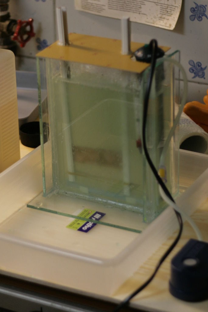
I know that I could have soldered that in a more beautiful way… 
As mentioned above, controlling the PWM for several LEDs is a lot of work for one small microcontroller. So is speaking the USB protocol. Together, these result in a lot of load on the device, so the communication with the device is not 100% reliable. More than 99%, though, at least in our tests.
SO BE WARNED: You should not use this device to control the state of your nuclear reactor. If you intend to use it in that way despite of this warning, please let me know…
Thanks!
I’d like to thank Objective Development for the possibility to use their driver for my project. In fact, this project wouldn’t exist without the driver.
And I’d like to give special credit to Thomas Stegemann. He wrote the PWM-stuff, and I guess it would have been nearly to impossible to me to write the rest of the project without his help since C isn’t my natural language.
About the license
Our work – all contents except for the USB driver – are licensed under the GNU General Public License (GPL). License.txt is a copy of the GPL. The driver itself is licensed under a special license by Objective Development. See firmware/usbdrv/License.txt for further info.
Download