This article hasn’t been in the blog until 2015, I took it from my old CMS.
The new adapter
The problem
When developing a prototype on a breadboard, it is not really possible to connect the ten-pin connector on it. I built myself some kind of an adapter cable to connect every pin onto the board.
As you can see, it’s really ugly and not quite stable. Plastic parts are getting weak during the soldering-process, and they are not really stable.
The solution
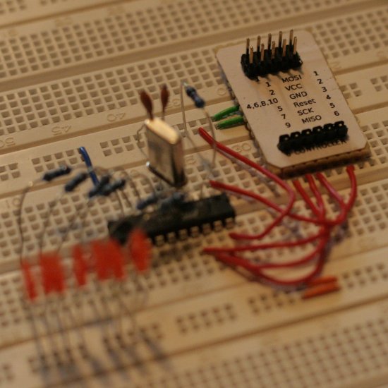
The adapter at work
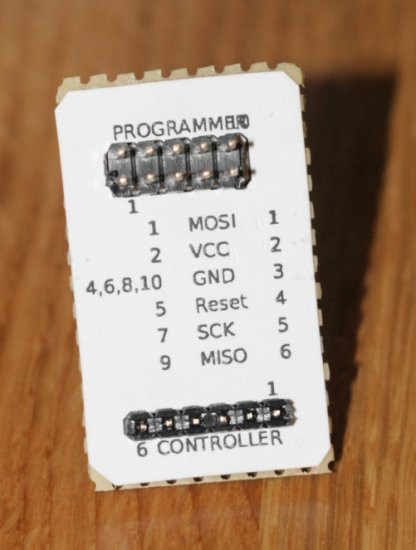
Beneath the printed cardboard, there is a simple circuit board. Otherwise there is a ten-pin connector for connecting the ISP-adapter, and a six-pin connector that is attached to the breadboard. I pressed the pins until they are almost fully beneath the board, so it fits tighter to the breadboard.
Oh, and the wires on the board’s lower side are painted. And not soldered really niceliy, but the mainthing is: it works!
Download
- adapter.ps.gz – The printed label, 11.2kB