Most pins are in use
I tested several boards when playing with this chip. Today, I want to describe one that goes with the name Witty Cloud.
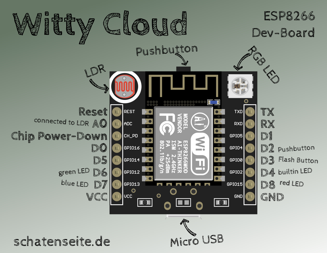
Basically, it’s a board with an ESP-12-F, a USB connector that delivers power, a little pushbutton, a LDR (Photoresistor) and a RGB-LED. So there’s plenty of hardware to play with. When you buy the module, you receive a stack of two PCBs. The lower one has a second USB connector, which is equipped with a serial converter. So it’s not only used as a power source, but also as a programming and debugging interface. Furthermore, there’s a reset- and a flash-button on the lower board. After programming, you just need the upper board, and you can even send newer firmware versions to it over the air (OTA).
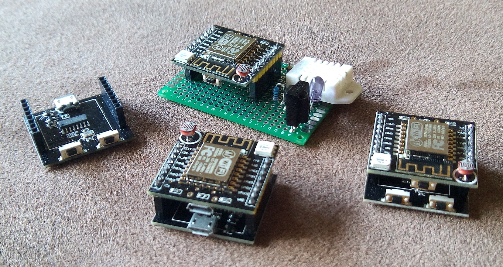
The lower board is only used for programming
Unfortunately, it’s not easy to find proper documentation for the Witty. So i scribbled the picture above, at first to have some kind of reminder for myself. So the pin labeled GPIO13 is connected to the blue channel of the RGB-LED, in the Arduino environment it’s called D7.
| Label | Pin (Arduino) | Purpose |
|---|---|---|
| REST | — | Reset |
| ADC | A0 | Analog input, connected to LDR |
| CH_PD | — | Chip Power-Down |
| GPIO16 | D0 | GPIO, freely usable |
| GPIO14 | D5 | GPIO, freely usable |
| GPIO12 | D6 | GPIO, green channel of RGB-LED |
| GPIO13 | D7 | GPIO, blue channel of RGB-LED |
| VCC | — | +5V power |
| TXD | TX | Serial interface |
| RXD | RX | Serial interface |
| GPIO5 | D1 | GPIO, freely usable |
| GPIO4 | D2 | GPIO, connected to pushbutton |
| GPIO0 | D3 | GPIO, connected to flash-button, not really freely usable |
| GPIO2 | D4 | GPIO, connected to blue LED on the ESP-Module |
| GPIO15 | D8 | GPIO, red channel of RGB-LED |
| GND | — | Ground |
I would be highly interested in a circuit of the board, and if you have any corrections or suggestions: just let me know.
Mein Fazit: ein echt interessantes Board. Wer mehr GPIO braucht sucht vielleicht lieber nach einem NodeMCU, wer sowieso einen LDR oder eine RGB-LED braucht sollte zugreifen. Ich habe mittlerweile einige davon hier, und eine Firmware mit der ich die Dinger hier im Haus verteilen möchte ist auch fast fertig.
Oh, das Bild habe ich übrigens mit einer Grafik aus diesem Projekt gemacht, das ist die Witty Cloud für Fritzing.