The module
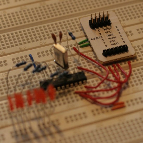
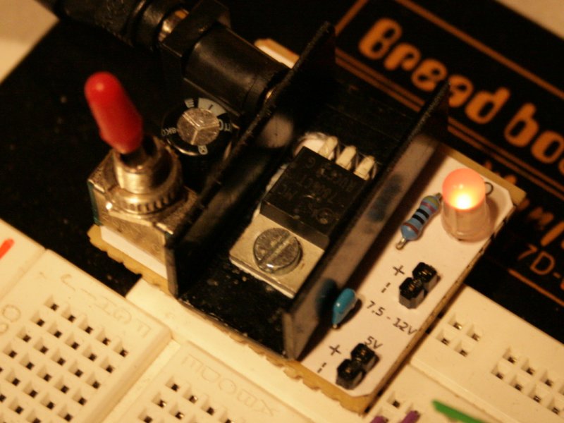
It is a little circuit you can use on your bread-board. Most microcontroller-projects run at 5V, but cheap power supplies lack this setting. So the first step in building a circuit on a bread-board is building the power supply. Over and over again.
This is not much fun, so I built this circuit to use it ‘en bloc’. After building it, I thought of inserting another diode to prevent wrong connection to the power supply. Too late for me, but you should put one in if you build one of these.
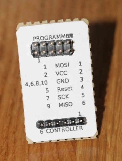
I created the label using Eagle, even if it is not derived from the circuit I used. Anyway: It’s in the downloadable package.
Plagiarism?
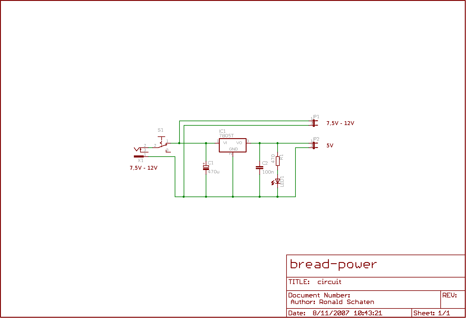
The circuit
I just can say: I did it before I saw the other articles. 
I suppose the idea is simple enough for anybody to have it…
Download
- 071018_breadpower.tar.gz – Circuit and labels, 65kB
See also…
- SparkFun – detailed description of a similar project
- Instructables – step-by-step-description of a similar project