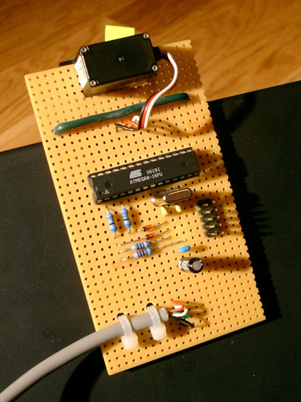
I took this article from my old CMS in 2015, it wasn’t in the blog until then.
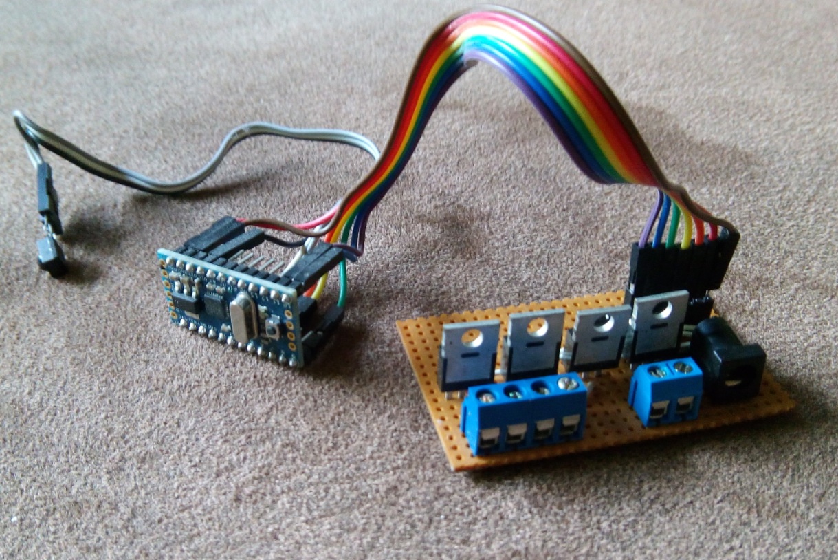
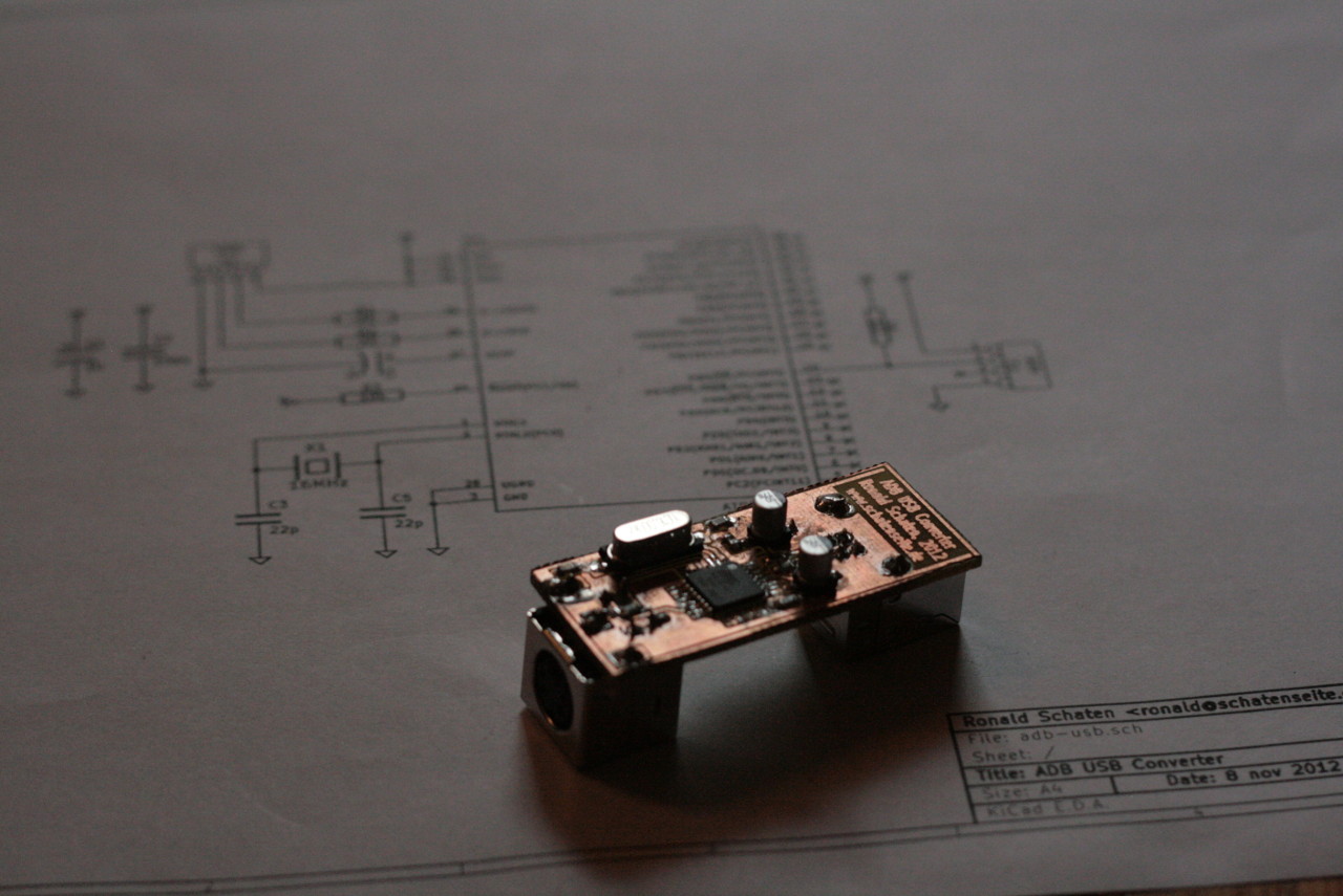
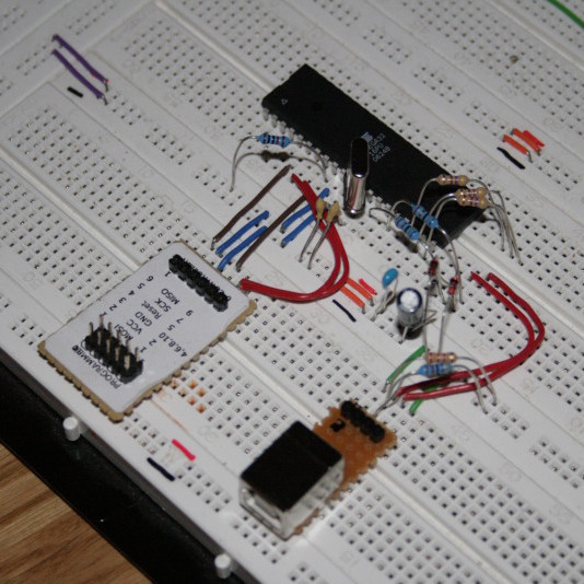
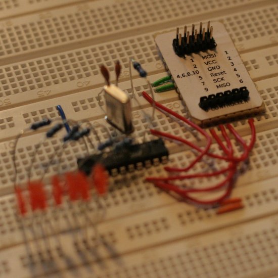
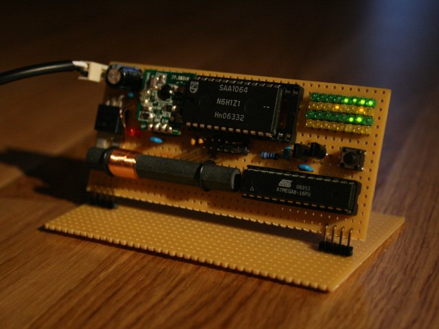
Breadboard in action
I haven’t done many microcontroller-projects till now, but more than one of the few projects I did involved controlling LEDs by pulse width modulation (PWM). Doing this for one or more LEDs is a stressful task for a little microcontroller, but if you want to do some other more or less complicated things while keeping LEDs at certain brightnesses is likely to ruin the timings that are used in the PWM. Not to talk about the program code, which gets more and more unreadable if you try to do several different things ‘at the same time’.
For my next project I need to fade some LEDs again, so I was looking for an easier way to do it. The plans include reading from memory cards, talking to real time clocks and displaying text on an LCD, so I’m almost sure that I won’t be able to reliably control the five channels I’m going to use.
The first plan was to use a ready-made chip. I looked around and the best thing I could find was one made by Philips (PCA something, I forgot the number) that can be controlled via I2C-bus. That part is able to control eight LEDs, but apart from ‘on’ and ‘off’ you can set the LEDs only to two different brightnesses. Those are variable, nevertheless, but it would be impossible to light one LED at 20%, one at 50% and one at 80%. Another drawback is that it is SMD-only, and my soldering-skills don’t including working with stuff that small.
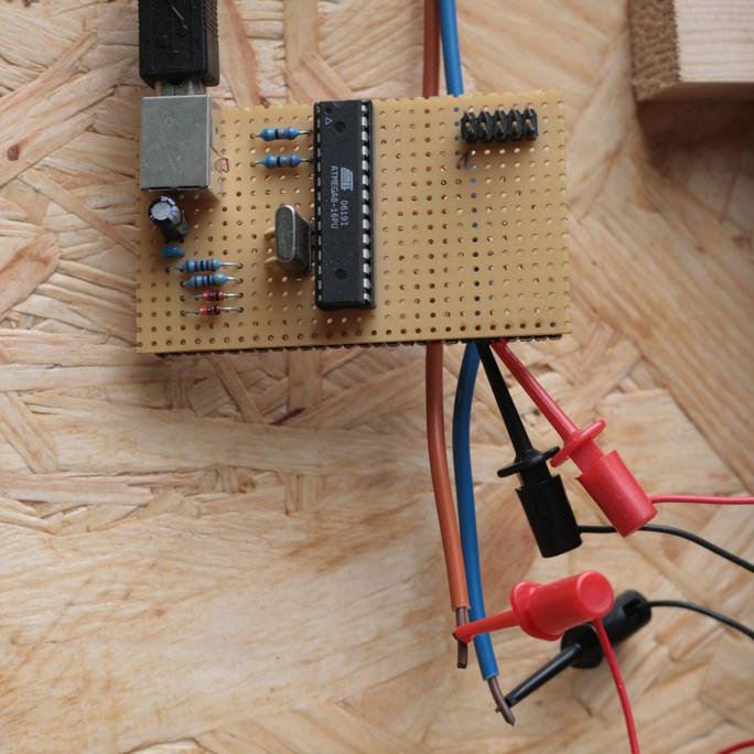
So the Idea was to set up a separate controller for LED-fading, that can be externally controlled, ideally via I2C-bus since I intend to use several other devices in my next project that can make use of the bus. So I set up an ATtiny2313 on my breadboard, clocked it with an external 20MHz-crystal and we tried to control as many LEDs as possible…
Pulse width modulation
Controlling the brightness of LEDs by PWM is a common technique, I used it myself in several projects.
The old way
Till now I used to switch on all LEDs that should light up at a level greater than zero, waited till the first of the LEDs has to be switched off, switched it off, waited for the next one and so on. After a certain time all LEDs are switched off, and I start again.
I try to visualize that with a little picture:
|
|
. . . . .| . . 1 *************************************************|************************ 2 *************************************** |************************ 3 ********* |********** 4 | 5 ***************************** |************************ |
In this example, a full cycle of the PWM would need 50 units of time. The first LED is switched on the full time (100%), the second for 40 of the 50 units (80%), the third one for ten (20%) and the fifth one for 30 units (60%). The fourth LED is off (0%). We see that after 50 units of time the modulation starts again.
The drawback of this technique is, that it’s slow. And for each additional channel you try to control, it gets even slower. We tried, but we weren’t able to control more than five LEDs in this way without them to start flickering to a visible amount.
We tried to create an array with all states of the process, so the PWM only would have to loop through the array and set the outputs accordingly. But that didn’t work either, because the used microcontroller doesn’t have enough RAM to store the array.
Thomas’ idea
After some tests that didn’t work out too well, Thomas had a great idea how to implement the PWM. It also works with an array for all states, but the states of the modulation are not displayed for the same time. The first state is displayed for one time-unit, the second one for two time-units, the third one for four and so on. In this way the LEDs are turned on and off more than once per cycle of the PWM, but that doesn’t hurt.
Let’s try to paint a picture again:
|
|
. . . . . . | . .. . . . . |.. . . 1 * |* 2 ** | ** 3 *** |*** 4 **** | **** 5 * **** |* **** 6 ****** | ****** 7 ******* |******* 8 ******** | **** |
So here we see a PWM with eight channels that are able to display up to 64 different brightnesses. Channel one is switched on for one unit of time, channel two for two units and so on. The most interesting thing is on channel five: the LED is switched on for one unit of time, switched off, and switched on again for four units of time.
Lets try a more complicated example — with brighter LEDs, too:
|
|
. . . . . . | . .. . . . . |.. . . 1 * *******************************|* 2 ** **************** | ** 3 ******* **************** |******* 4 *******************************| 5 * **** **************** |* **** 6 *************************************************************| ********** 7 **************************************************************|*********** 8 ************************ | **** |
The channels 1 to 8 have the brightnesses 33, 18, 23, 32, 21, 63, 64 and 24.
Brightness 75 on the oscilloscope
The advantage of this technique is that on the one hand you have to save a limited number of states (six states in the example), and the looping through the states is very simple: state n is sent to the output pins, then we wait for 2^(n-1) time units, then the next state is sent.
Each state represents the bit-pattern that has to be sent during one step. In other words: one column out of the above picture at the start of a new time period. So in this example, we have six states: 01010101, 01100110, 01110100, 11100000, 11110110 and 01101001. The first one is displayed for one unit of time, the second one for two units, the third one for four units and so on…
Using this technique has the advantage that adding more channels does almost nothing in terms of system load. The only time that the algorithm has to do actual calculations is when a new value has been delivered and has to be converted into the states. So using this algorithm, it is possible to show different brightnesses on all free pins of the controller. With an ATtiny2313 that means that you can fade 13 different LEDs while still talking I2C to communicate with other devices!
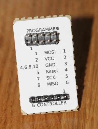
I2C communication
Speaking I2C is no rocket science, but since one has to do a lot of bit-shifting when implementing it, I took a ready-made library.
The one I used is written by Donald R. Blake, he was so kind to put it under GPL and post it to avrfreaks.net. You can find the original post in a thread called ‘8 bit communication between AVR using TWI‘, and some additions in the thread ‘I2C Slave on an ATtiny45‘.
Thanks for the great work, Donald! And for putting it under a free license.
Since his package seems to be only available as a forum-attachment, and I’m not sure for how long that will be, I included it into the tarball of this project.
Usage
You should be able to use this device in the same way you would use any other I2C-slave:
Connecting it
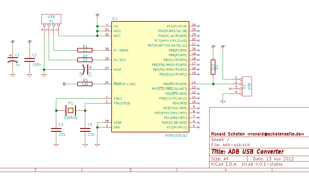
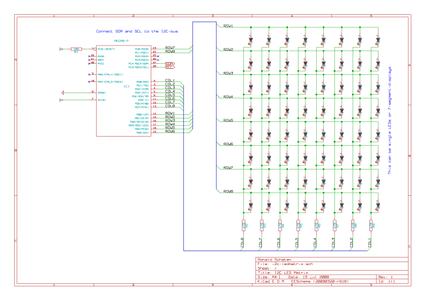
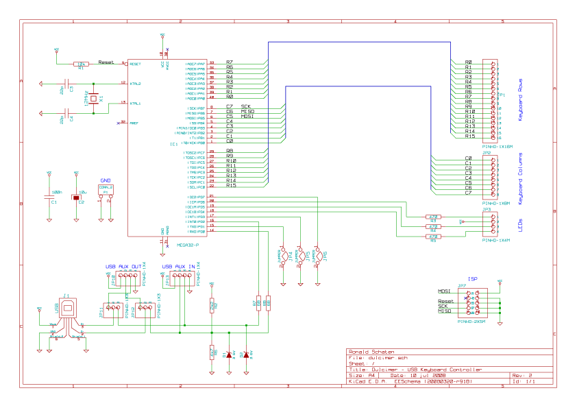
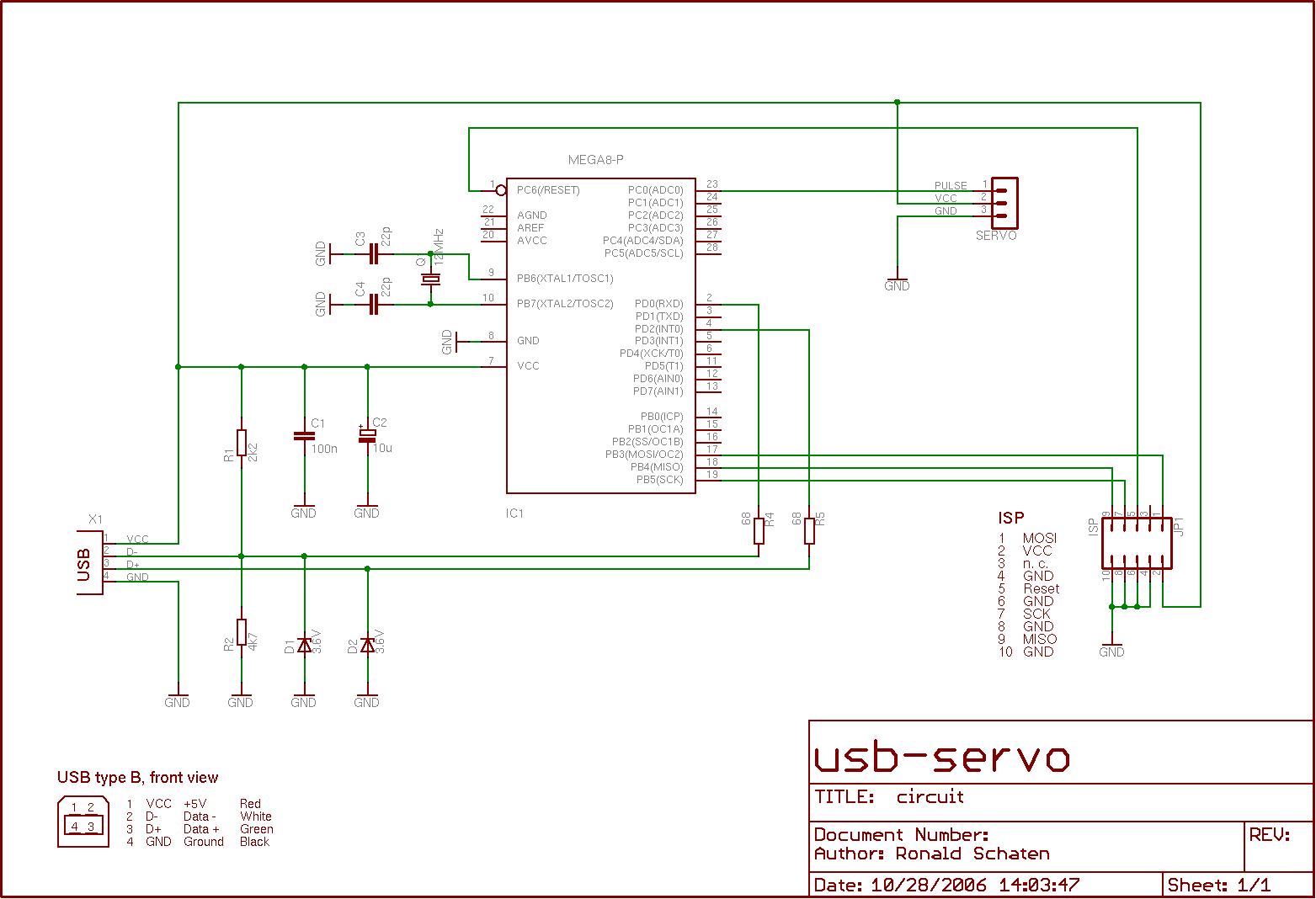
The controller needs to have the following pins connected in the circuit:
- Pin 1 – Reset – should be connected to VCC with a 10k-resistor
- Pin 4 and 5 – XTAL1 and XTAL2 – connected to a 20MHz-crystal, using 22p-capacitors against GND
- Pin 10 – GND – Ground
- Pin 17 – SDA – I2C-data
- Pin 19 – SCL – I2C-clock
- Pin 20 – VCC – 5V
Your I2C-data and -clock lines should be terminated by 4,7k-resistors to pull up the lines. All the other pins can be used to connect LEDs. They are arranged in this way:
- Pin 2 – PD0 – Channel 0
- Pin 3 – PD1 – Channel 1
- Pin 6 – PD2 – Channel 2
- Pin 7 – PD3 – Channel 3
- Pin 8 – PD4 – Channel 4
- Pin 9 – PD5 – Channel 5
- Pin 11 – PD6 – Channel 6
- Pin 12 – PB0 – Channel 7
- Pin 13 – PB1 – Channel 8
- Pin 14 – PB2 – Channel 9
- Pin 15 – PB3 – Channel 10
- Pin 16 – PB4 – Channel 11
- Pin 18 – PB6 – Channel 12
Talking to it
For my tests I used an ATmega8 as I2C-master with the library written by Peter Fleury. You can find it on http://jump.to/fleury. Thanks to him for putting it online!
The typical send function looks like this:
1 2 3 4 5 6 7 8 9 10 11 12 13 14 15 16 17 18 19 20 21 22 23 |
#define I2C_FADER 0x10 void sendi2cBytes(uint8_t address, uint8_t brightness) { // address: number of the LED to set (0..12) // brightness: value between 0 and 127 // start the communication... i2c_start_wait((I2C_FADER < < 1) + I2C_WRITE); // write a byte with the address. we want the highest bit of the // address to be 1, so the slave can be sure that this is an address. i2c_write(address | 0x80); // calculate the actual duration the LED should light up. we could do // this on the slave's side, but we assume that the device is more // flexible when it is done on the master side. uint16_t duration = (brightness + 1) * (brightness + 1) - 1; // calculate the low- and the high-byte and send it. note that we split // the duration into 7-bit-values, not 8 bit! in this way the highest // bit of the transferred bytes is always low, allowing the slave to // recognize the transmitted bytes as values, not as addresses. i2c_write(duration & 0x7f); // low byte i2c_write((duration >> 7) & 0x7f); // high byte // stop the communication... i2c_stop(); } |
Examples
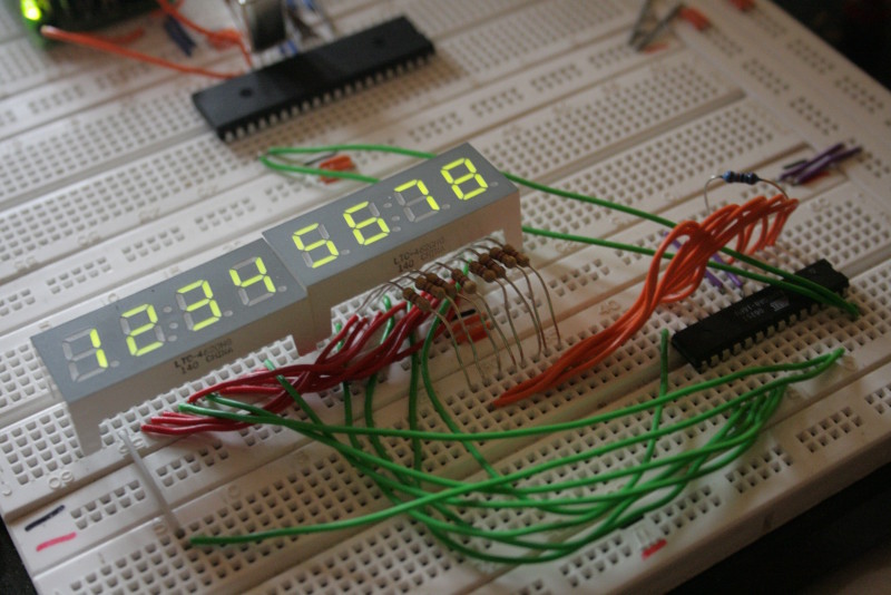
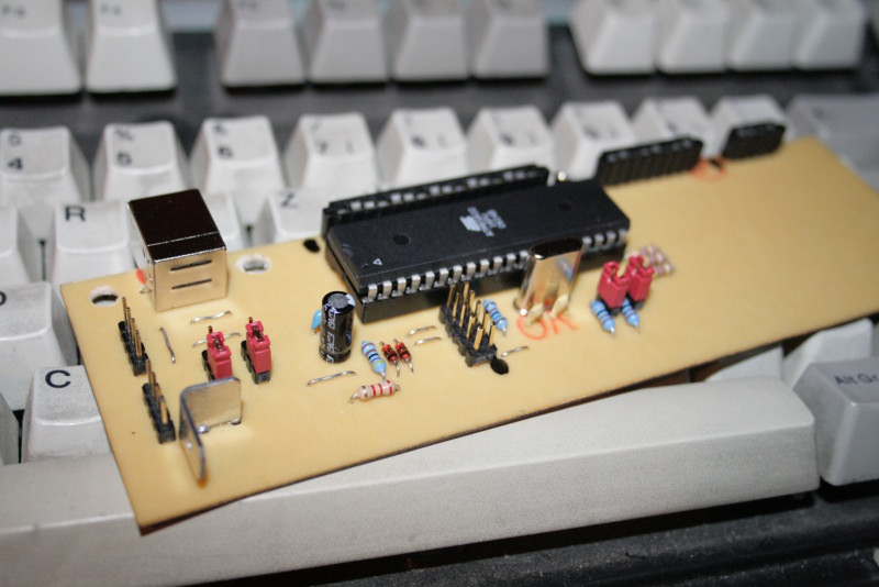
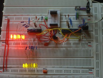
I2C-Fader on testboard
Here, you see all LEDs fading at different speeds.
The code running on the I2C-master to generate this pattern looked like this:
1 2 3 4 5 6 7 8 9 10 11 12 13 14 15 16 17 18 19 20 21 22 23 24 25 26 27 28 29 |
void sendi2cBytes(uint8_t address, uint8_t brightness) { i2c_start_wait((I2C_FADER << 1) + I2C_WRITE); i2c_write(address | 0x80); uint16_t duration = (brightness + 1) * (brightness + 1) - 1; i2c_write(duration & 0x7f); // low byte i2c_write((duration >> 7) & 0x7f); // high byte i2c_stop(); } void fadeall(void) { uint8_t i = 0; int16_t brightness[13]; int16_t speed[13]; for (i = 0; i < 13; i++) { brightness[i] = 64<<8; speed[i] = random() & 0xff + 0x40; } while (1) { for(i= 0; i < 13; i++){ sendi2cBytes(i, brightness[i]>>8); brightness[i]+= speed[i]; if(brightness[i]>>8 > 127 || brightness[i]>>8 < 0){ brightness[i]-= speed[i]; speed[i] = -speed[i]; } } timerPause(1); } } |
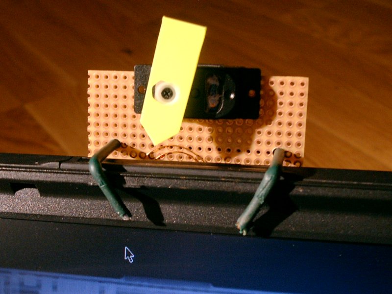
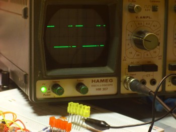
Visible PWM
Here you see the signal of one LED fading from 0 to 127. Unfortunately, my oldtimer-oscilloscope doesn’t trigger correctly in the middle part.
This is the code that ran on the I2C-master:
|
|
void sendi2cBytes(uint8_t address, uint8_t brightness) { i2c_start_wait((I2C_FADER < < 1) + I2C_WRITE); i2c_write(address | 0x80); uint16_t duration = (brightness + 1) * (brightness + 1) - 1; i2c_write(duration & 0x7f); // low byte i2c_write((duration >> 7) & 0x7f); // high byte i2c_stop(); } void fade(void) { uint8_t i; for(i= 0; i < = 127; i++){ sendi2cBytes(0, i); timerPause(100); } } |
Drawbacks
Till now, the device worked in all situations I tested it in. So far everything is fine.
I guess that, compared to the ready-made off-the-hook-parts that controls LEDs via I2C, this module is a bit slow. I can’t see any flickering in the LEDs since they are still switched very fast (about every 6ms, which would result in a 166Hz flickering — too fast for me).
Thanks!
Once again, special credits go to Thomas Stegemann. He had the great idea for the PWM-algorithm, and I am always astonished by the patience he has to show me how to do anything complicated in a sick language like C…
About the license
My work is licensed under the GNU General Public License (GPL). A copy of the GPL is included in License.txt.
Download