I didn’t have this project on the blog in 2008, I copied it from the old CMS in 2015.

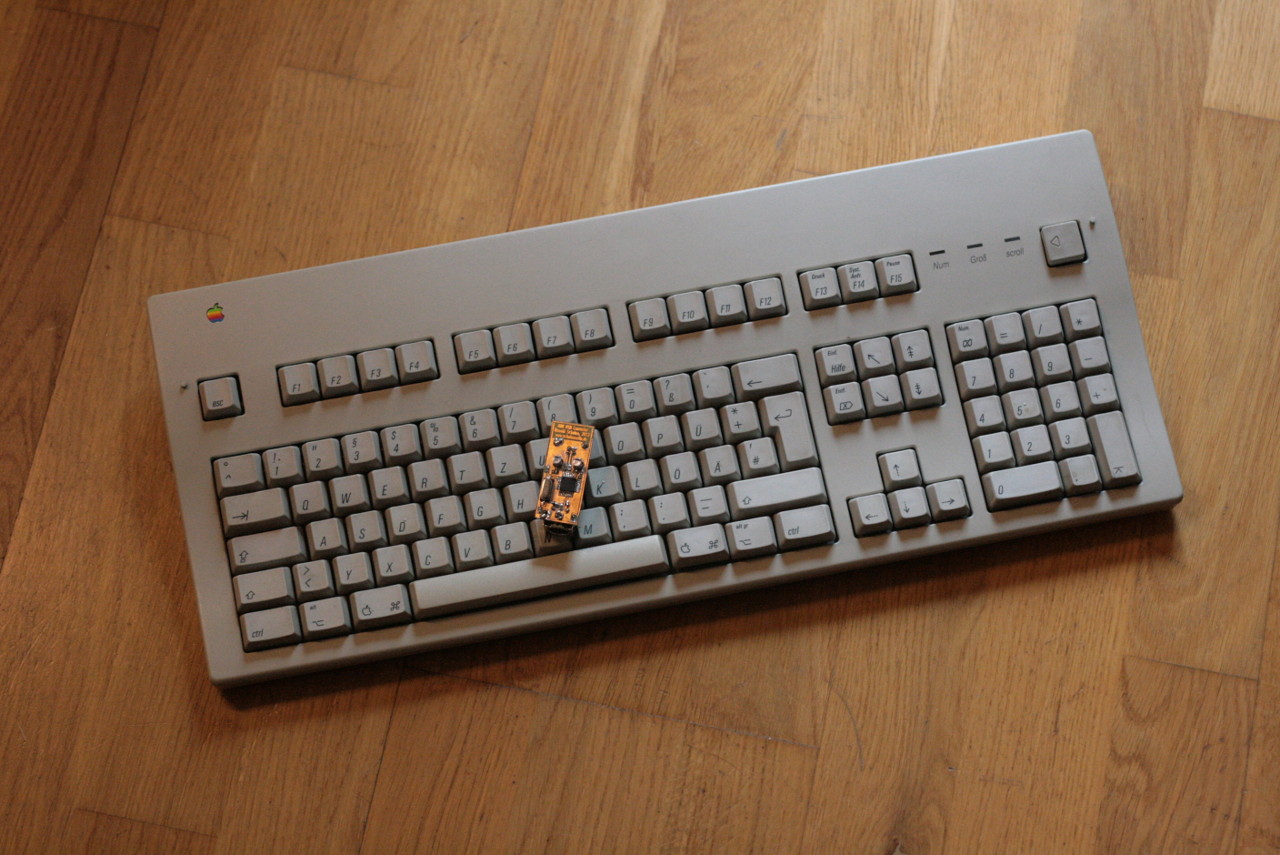
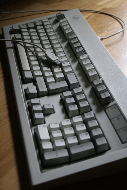
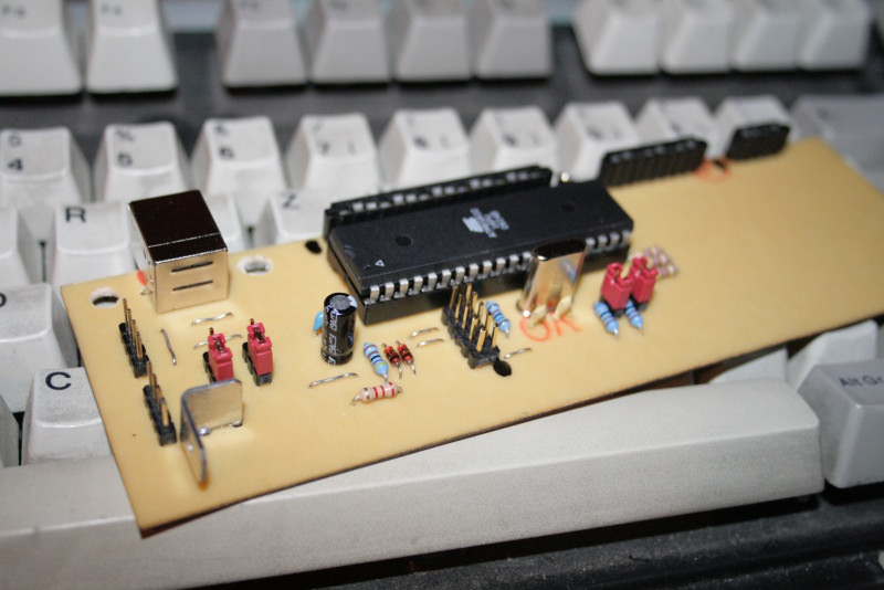
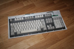
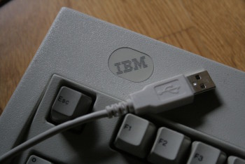
Looks like the day it was made — except for the cable
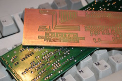
A ‘hammered dulcimer’ is a musical instrument, its german name is ‘Hackbrett’. But you also can loosely translate ‘Hackbrett’ to ‘hackboard’, which I think is a great name for this kind of keyboard. A funny fact on the side is, that the name ‘Dulcimer’ originates from the latin ‘dulce melos’, which means ‘sweet sound’. If you ever heard someone type away on a Model M, you know why I chose this name… 
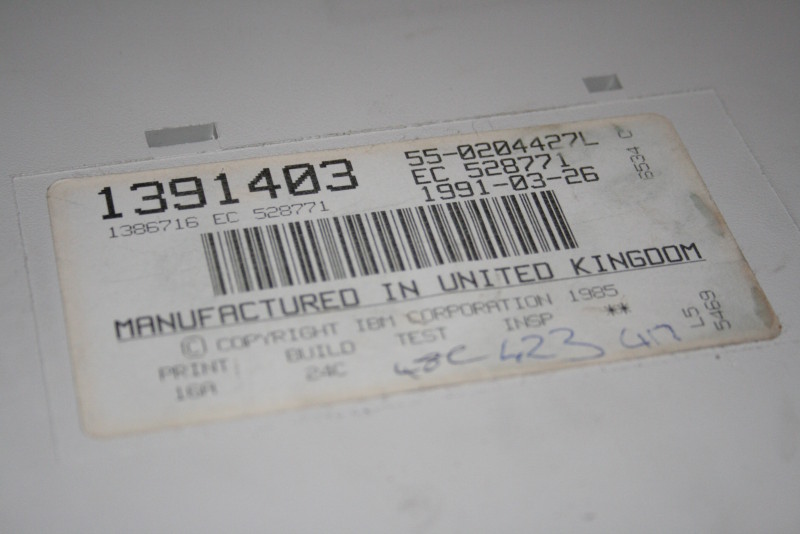
A computer keyboard can be a very personal utensil. Especially if it is an extraordinary well built one, like for example the IBM Model M. The Model M design dates back to 1984, but it still has many fans even nowadays. It came with the usual keyboard connectors. First the old 5-pin one, later a PS/2 plug. Unfortunately is that, at least to my knowledge, they never released a version with USB.
A friend of mine knew that I already had built other USB-devices, and one of them even acted as a keyboard (it isn’t really a keyboard, but that’s a different story… ). He is a big fan of the Model M, so he asked if I could put new life in one of his old keyboards, which had a broken circuit inside. And this is the result…
Hard- and Software

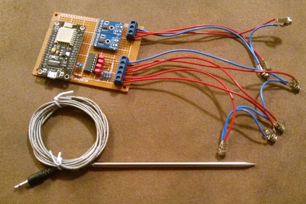
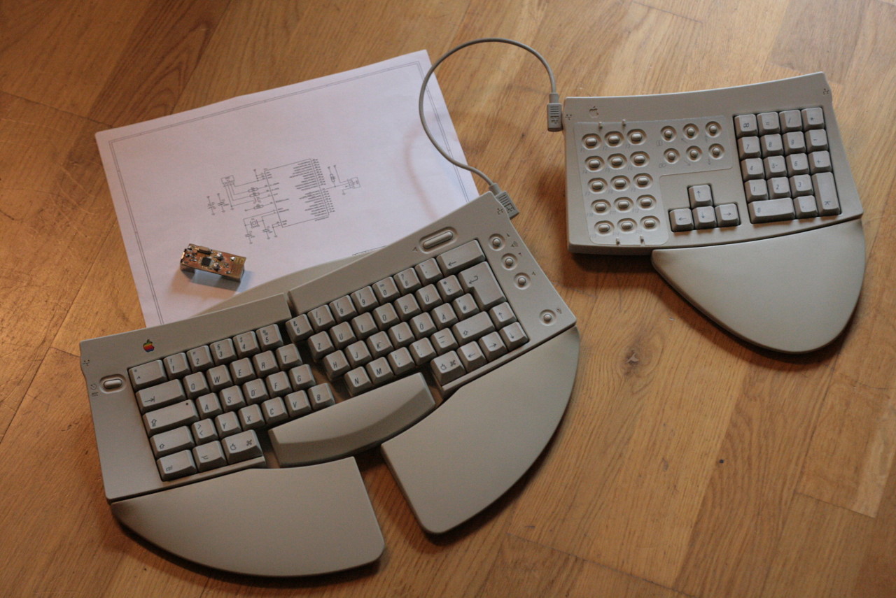
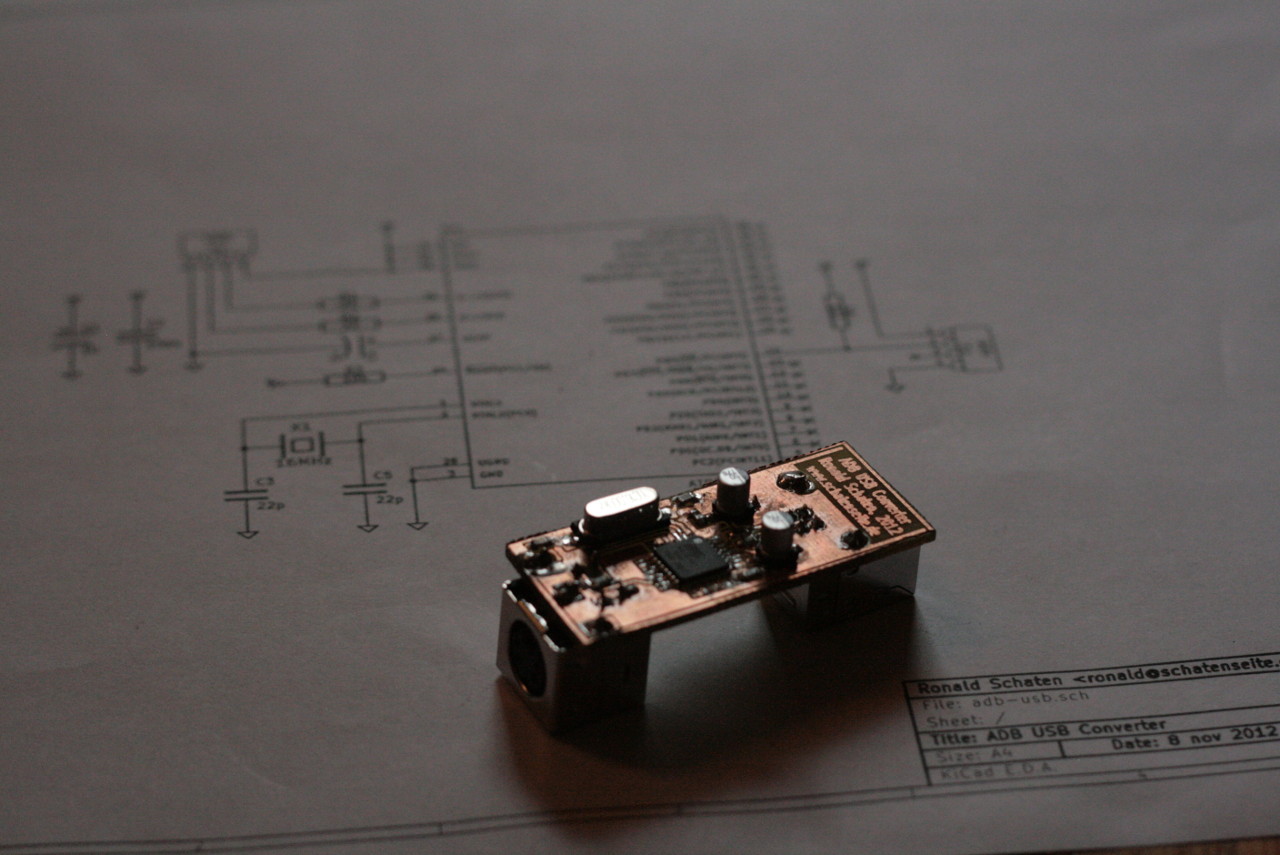
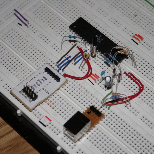
A first prototype
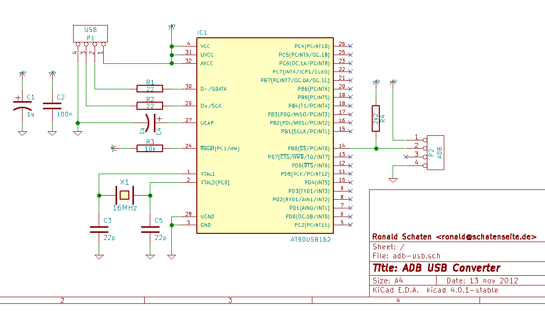
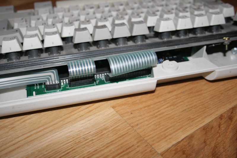
The main part of a computer keyboard circuit is the key matrix. You can imagine it as a number of keys, placed on a raster of horizontal (rows) and vertical (columns) wires. In the case of a Model M keyboard, we have a matrix of 8×16 lines. Eight columns in 16 rows, or the other way around, depending on how you look at it. Each key is connected to one column and one row. If you press the key, it will connect the column and the row on it’s crossing of the lines.
Connected to this matrix is a keyboard controller. That’s a chip with a number of I/O-lines to detect the state of the matrix, and on the other side an interface that enables it to talk to the computer. Oh, and not to forget: it also has three output lines to drive the LEDs for Num-, Caps- and Scroll-lock.
What I did in this project is, that I dumped the keyboard controller chip and its circuit, and replaced it by an ATmega32 and my own circuit. The ATmega scans the matrix for keyboard activity, controls the LEDs and talks to the computer.
-
-
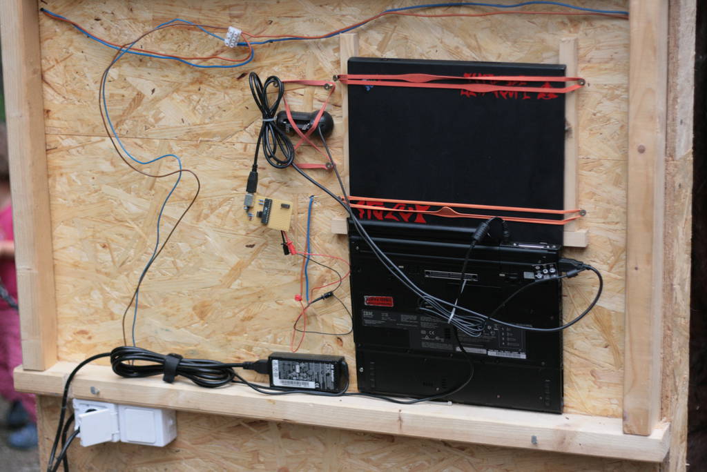
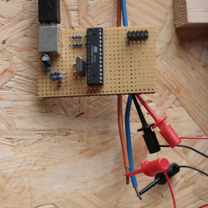
Well built
-

-
The Matrix
-
-
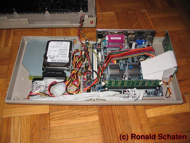
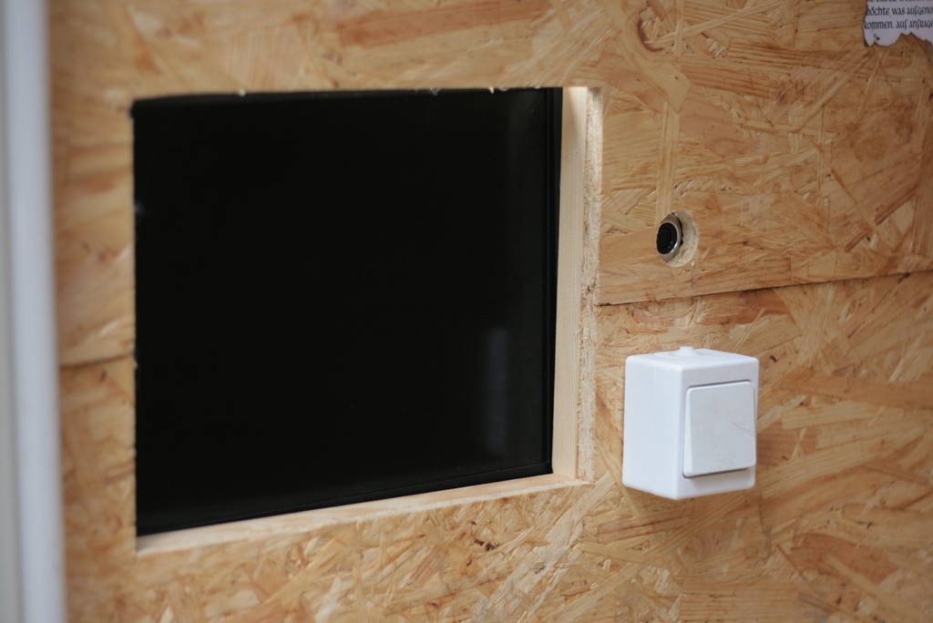
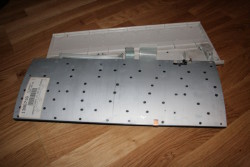
Solid base
For further convenience, I added a boot-loader. With that, it is possible to update the keyboard’s firmware without disassembling it, and without the need for a dedicated programmer.
Other Hardware?
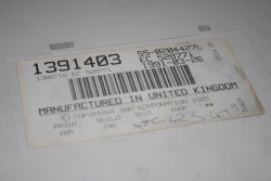
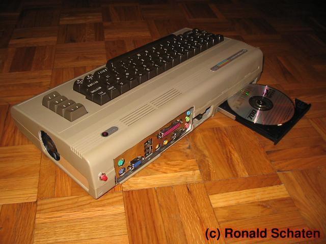
Antique
As mentioned, the controller in this project is just connected to an ordinary keyboard matrix. You can find this kind of matrix in all kinds of keyboards, from key-telephones over good old hardware like the Commodore C=64 or the Schneider CPC, keyboards with non-PC-connectors like those made by Sun, to modern hardware that could need a few more features.
Till now, I just made a PCB layout for the IBM Model M, but I intend to modify at least a Sun keyboard. In order to do that, I expect having to refactor the key-scanning, since the key-matrix is not 16×8. The positions of the keys on the matrix will be different, I’ll have to re-engineer that. And of course, I’ll have to make another PCB.
Features
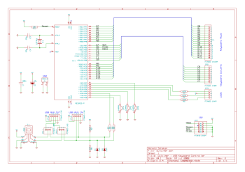
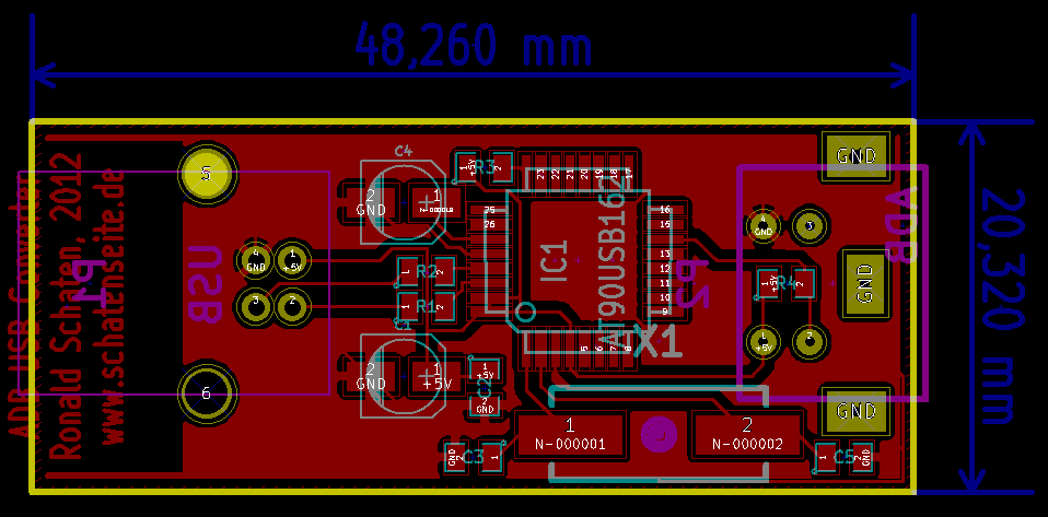
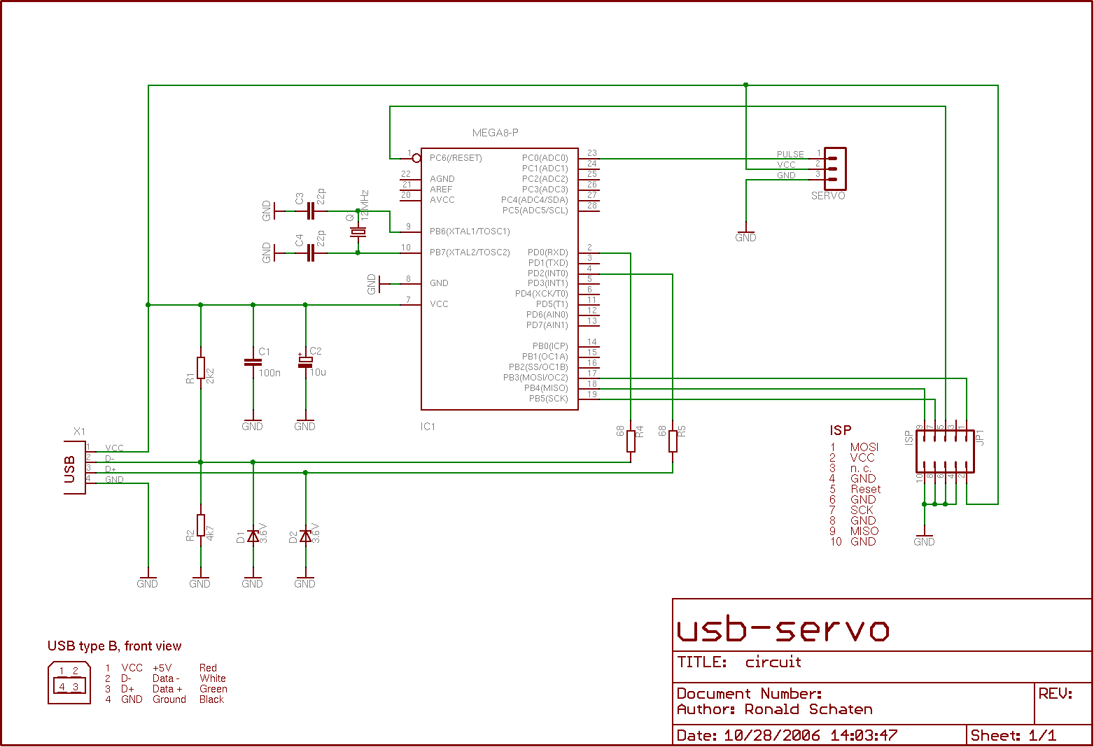
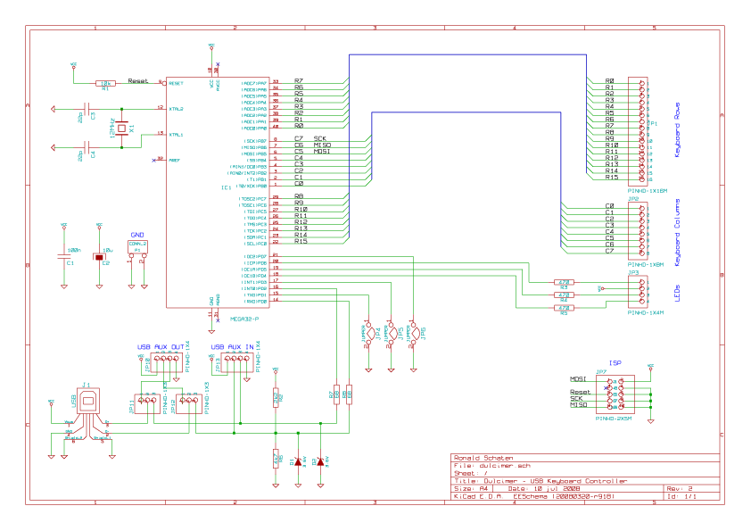
Powered by Kicad
At the moment, the keyboard should be able to do everything that the average off-the-shelf-keyboard can do. But there are many features that are possible, regarding the fact that the ATmega32 is absolutely bored till now. You can think of ‘magic keystrokes’ that turn some hidden features on or off, like for example:
- send complete phrases on one keystroke
- ‘autofire’ feature on keys that don’t repeat normally, for example Alt+F4
- change keyboard layout without reconfiguring the computer
- turn bouncing keys on or off, to annoy other people using your computer
- random caps lock function
- use arrow keys as mouse, without having to include a special driver in the OS.
With a little tweaking on the hardware side, there should be even more possibilities:
- turn the oldtimer-keyboard into a supermodern wireless bluetooth one
- implement keylogger-funktionality, using for example an SD-card
- include an USB-hub into the keyboard
-
-
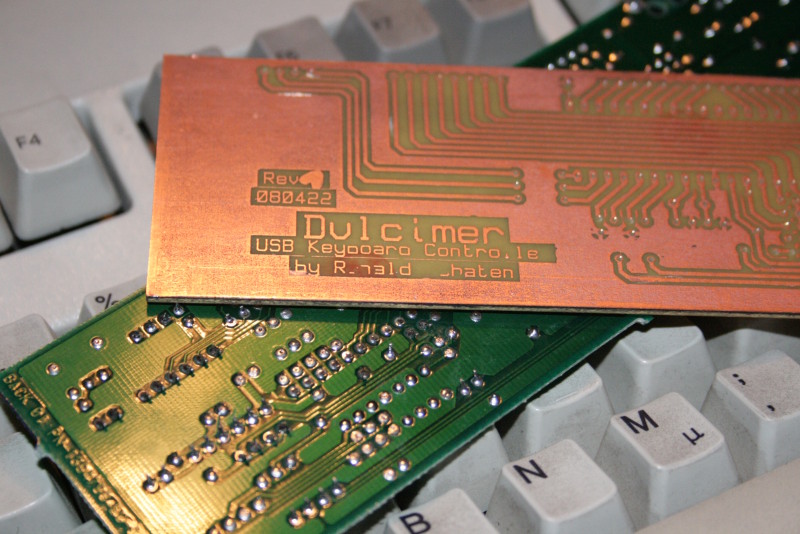
My first own PCB design
-

-
That’s how it looks
If you are just a little like me, it won’t take you much brainstorming to come up with own useful — or even better: useless — ideas.
Usage
Connect the keyboard to the USB-port. All LED should flash up to indicate that the device is initialized.
Then you can use the keyboard as always. If additional features get implemented, you will be able to use them in their respective ways.
Drawbacks
I don’t know if and how keyboard manufacturers face the problem of ghost keys, I didn’t take special measurements for this. I hope that the engineers at IBM distributed the keys on the matrix in a way that minimizes this problem. Don’t misunderstand: I haven’t experienced that on this keyboard, but I know that it’s a common problem on key-matrixes.
Thanks!
Modern oldtimer
I’d like to thank
Objective Development for the possibility to use their driver for my project. In fact, this project wouldn’t exist without the driver.
I took great inspiration from Spaceman Spiff’s c64key, this software is based on his ideas.
Further credits go to xleave, who etched the PCB for me, and also answered many stupid questions about electronics I had during the last few years.
And of course I’d like to thank FaUl of the Chaostreff Dortmund who gave me the idea for this project.
About the license
My work – all contents except for the USB driver – is licensed under the GNU General Public License (GPL). A copy of the GPL is included in License.txt. The driver itself is licensed under a special license by Objective Development. See firmware/usbdrv/License.txt for further info.
Download
See also…
- clickykeyboards.com – dedicated to IBM Model M
- RUMP – practically the same project, a parallel development
- Geekhack – protoboard version, based on Dulcimer
 Lieber auf Deutsch?