Deutsch Lieber auf Deutsch? Hier lang.
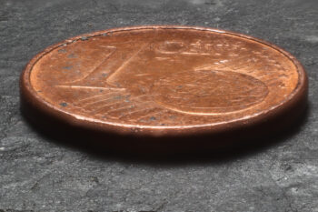
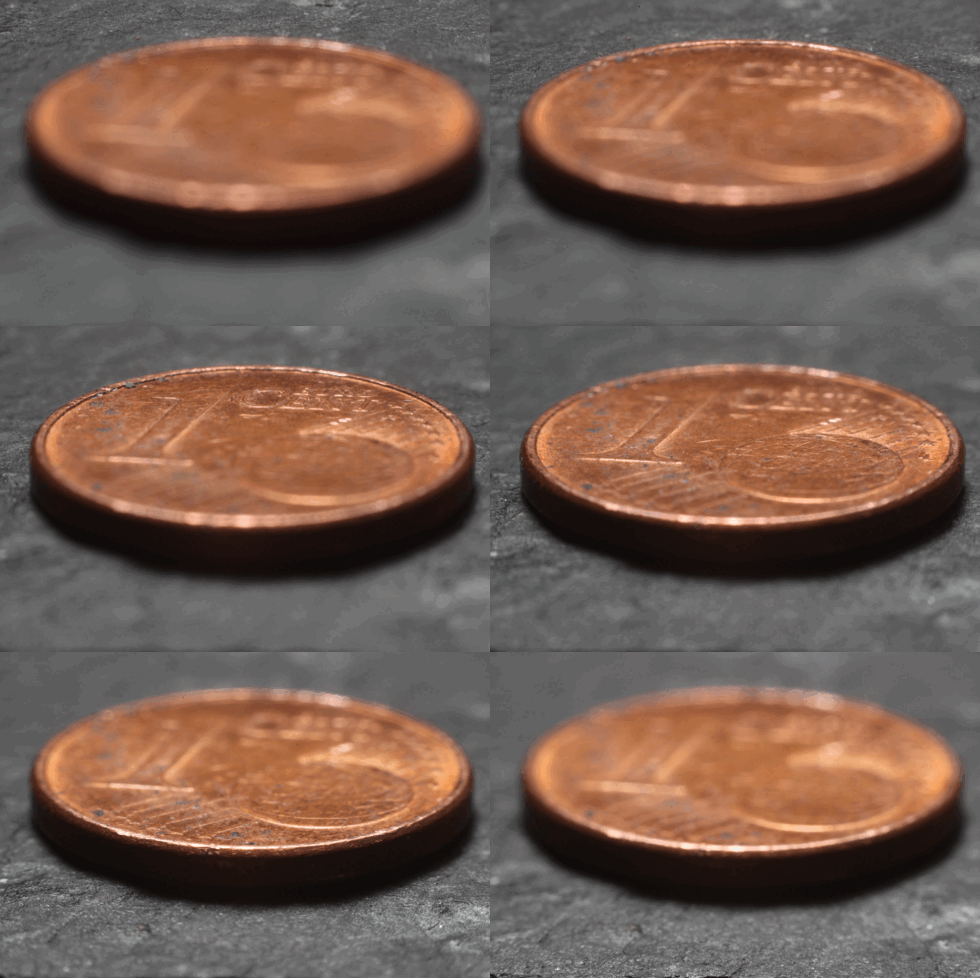
One Euro-Cent, stacked from 30 images

One of my biggest – although in recent years very neglected – hobbies is photography. I have always been attracted by the technology and the possibility to explore its limits. Examples of this are the high-speed flash trigger (German only, sorry) I built almost 20 years ago (at that time without a microcontroller (!)), or my darkroom where I pushed the good old Kodak T-Max P 3200 far beyond its limit.

A topic that has always fascinated me is macro photography. With my first SLR – an heirloom from grandpa, a full-manual camera from Revueflex – I had already found a set of extension tubes. Simple ones, with M42 connection, but they got me hooked. After entering the EOS world, I bbought an adapter to use the tubes and lenses on the newer camera, then at some point at a photo fair also an old bellows. And another one. :-)

Boss Monster Depth of Field

One problem when taking macro photos, regardless of which technique you use to go to the extreme, is the lack of depth of field. It’s not uncommon to be dealing with millimeters or even fractions of millimeters. “In my day,” that is, in the analog photo world, you couldn’t do much against that. Nowadays, however, people shoot digitally. So at some point, someone came up with the idea of focus stacking: you don’t just take one picture, you take a whole stack of pictures. Each with the focus in a different plane. You then load this stack into an image editor and tinker with it until you have only the parts that are in focus – and thus an image with a significantly extended depth of field.

Of course, you don’t always want to spend half a day clicking around in Gimp, so resourceful developers have written programs that do the job. There are commercial solutions, but I stuck to open source.

Stack photography with Arduino

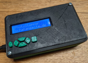
PhotoStepper
PhotoStepper

What I built is not new. You can buy such devices from various commercial manufacturers, there are also quite a few well documented tinkering projects. Some of them even with practically the same hardware I used. Why did I do it myself anyway? Simply because I wanted to know if I can do it. :-)

So I fished an old Arduino Uno out of the big box of leftovers, plus a LCD keypad shield I bought sometime without really knowing for what. With a stepper motor driver (A4988) and a motor I still had from another project I could try out how it all works together. I could have connected the Arduino directly to the cable release connector of my camera, but that was too exciting for me, considering the 12V supply voltage. So I did that using two optocouplers (PC817).

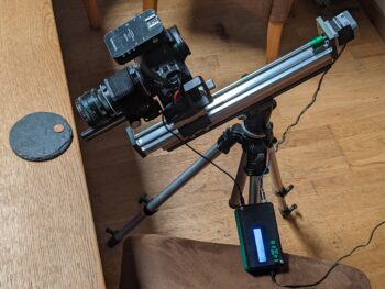
My rig for focus stacking

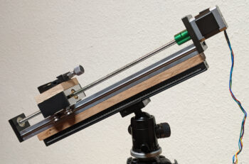
The prototypical tests worked well, so I printed a case and looked for some suitable mechanics. I was able to get a linear actuator including motor practically as a bargain. Plus a rail for mounting on the tripod and a clamping plate to mount the camera on the slide. And since I am more a carpenter than a mechanic, the connections between the parts are made of rustic oak. :-)

The parts are just like my tripod Arca-Swiss compatible (another term that did not exist “in my time”), so the base plate can stay on the camera and everything is quickly and stably set up.

Photo Session

Shooting setup, still without the flash

My first subject – a rather dirty Euro-cent – was not original, and the setup is quite crude. Camera with bellows and a 58mm lens from my grandpa’s heritage on the linear drive, a radio triggered flash facing the “model”.

I setup the camera and roughly focused on the coin. Then I set camera and flash to manual mode and selected the right exposure. Up to here nothing unusual.

Then my new device came into play: I moved the camera forward a bit so that the plane of focus was clearly behind the coin. Then I set the device to take 30 pictures, each 1mm apart. So I covered 3cm – enough for the coin, but when you look at the finished shot not enough to stay sharp to the top of the image. Too bad, but it’s just a test.

Cent piece, 30 focus levels

One minute – and a dance of joy behind the camera – later, 30 pictures are in the can.

I drag them over to my computer and edit them with two tools: align_image_stack from the Hugin package makes sure that all images are aligned and resized. The camera moves away from the subject during the shooting, so the subject gets smaller and smaller. This would greatly avert the stacking.

This is done by enfuse from the Enblend project. And it does it amazingly well, I think. Not perfect, though: at the top of the image there are still some artifacts from the processing. But really amazingly good. Especially for a first attempt.

The whole she-bang?

I’ve posted the complete project, including the source code and a description of the electronics.

All the info is here.

There you can have a look at everything in detail, and I’m always open for improvements.

Now what…?

To be honest, I don’t really have anything important to photograph with this thing. I have a few ideas, but I was mainly interested in building something like this. Done. Check. :-)

I also know that this is not a groundbreaking invention. I know that there are some modern cameras that already have a focus stacking function built in. If you really need something like that, you will probably go for such a model. My “oldie” from 2009 can only do that with this tool.

Since I just control a stepper motor and the camera with the device, I can imagine to operate it with some kind of a lazy susan. So I could take controlled photographs from all sides. I don’t know yet what I would need that for, but maybe this will develop again sometime in the direction of photogrammetry, so maybe a tool for creating 3D models. Let’s seeā€¦

Deutsch Lieber auf Deutsch? Hier lang.

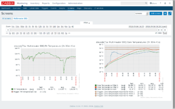
BBQ temperatures in Zabbix

BBQ temperatures in Zabbix

Unfortunately, this project is still work in progress. But I want to tell of the first test run anyways. The electronics didn’t do exactly as it was supposed, but you see where this is going.

About two years ago, I built a prototype of a BBQ thermometer, which I showed here (german only, sorry). It really was just a quick hack, not really intended for repeated usage. I have learned a lot since then, and now I want to build something like that, but this time as a ‘real project’.

Being able to measure core temperatures of multiple pieces of meat, I didn’t have to think about the project’s name for long: Multimeater! :-D

The Hardware

The Hardware

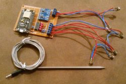
Like some of my last projects, this is based on an ESP8266-module, with software developed in the Arduino IDE. So it already runs WiFi. My firmware is — as in some of my other recent projects — based on the Homie-framework. It sends collected values via MQTT to my broker, from there they are delivered to Zabbix. Values are measured with two high temperature sensors each connected to a MAX6675, and four common meat thermometers on a MCP3208.

Six temperatures? Yes. The plan is, to acquire the inner temperature of the pit on two positions. Under certain circumstances, these temperatures can be too high for the meat sensors. So I take two separate sensors for this, one on each end of the pit (which is a bit lengthy on a smoker, so there really is a relevant bit of a temperature drop in between). And with four meat thermometers I can monitor core temperatures of — you guessed it — up to four pieces of meat.

Zabbix is usually used as a monitoring software for server systems. But it doesn’t just work in enterprise environments, I am collecting some… let’s say unusual values at home. ;-)

In this case, I just used it to see graphs of the temperatures. But if I’m really starting to smoke me a pulled pork over night, I can tell Zabbix to wake me up if temperatures are out of a predefined range.

As mentioned, today’s run was just a test. And of course, several things didn’t work out as they were planned. I had a problem with the high temperature measurements in the pit. Those values turned out to be completely useless. But since I just bought three pieces of meat for today, I was able to use the fourth meat sensor for the pit temperature. Then I misplaced the sensor in my piece of ham, so the graph looks a bit strange. And to top all this off, heavy rain poured down during the test. Currently, there is no roof over the smoker, so that didn’t make it easier, either.

All in all, everything looked quite promising. I keep bringing this forward, and as soon as I really get it to work I’m going to publish it here, of course with circuit and firmware.

Oh, and since I’m sure that I’ll get that question: technical problems aside, I had some awesome pieces of meat from this test. Everybody really enjoyed it. :-D

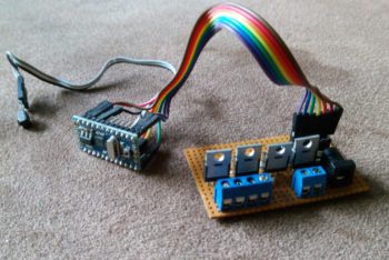
The circuit as it ran for two years

The circuit as it ran for two years

Normally, it would make much more sense to publish a project when it is done. In this case, I was sure that I had done exactly that. It’s just a few days since I realized that I didn’t. Funny, it’s been exactly three days before I replaced the project by something else. However, even if it’s a bit late, I’ll deliver…

In early 2014, we renovated our living room. One wall got a rocky structure, and I thought that was the perfect place for a grazing light from above. This screamed for LED-strips. Fooling around with my daughters, I mentioned a plan of installing a pink light. The plan was to go with warm-white, but they insisted on a pink light… two against one, I was in defense position. :-)

Theoretically, a simple RGB-strip can be made to give white light. Practically, most times that’s a really ugly tone of white. So I installed a warm-white strip next to the RGB one. The controller that was delivered with the RGB-strip wasn’t able to power this combination, so I needed a RGBW controller. I couldn’t find an affordable one, so I had to build it myself.

That's how it works

That’s how it works

If I remember correctly, that was my first Arduino project. And it was surprisingly easy to do. I built a first prototype with an Arduino Uno, and with the great infrared receiver library by Ken Shirriff I was able to control a RGB and a white LED after just two hours. Using my trusty Logitech Harmony, which also controls the rest of my media system.

The second prototype I built using MOSFETs, to test how I would be able to control the LED-strips with an Arduino. They are powered with 12V, after all.

The final build is pictured on the photo above: an Arduino Pro Mini (the one without USB interface), and a simple PCB that is wired for controlling the strips. There’s an infrared receiver wired to the Arduino. Initially, that was a TSOP31238, but I fried it just before finishing the project by wiring it wrong. Wanting to get this done, I gutted an old DVD player. I don’t have the slightest idea what type of receiver this is, but it works. :-D

That means: it did work. Almost exactly for two years. Till today. Now it’s obsolete — as I said. Sources and documentation go by the name of IRlicht, I published today.

Oh, and if that’s of anybodys concern: until today, the lamp was used almost only in the white mode. The colors — and especially the color changing modes — were used only for testing and for showing how it works. It was used rarely enough that I had to look up the used keys in the source code…

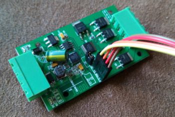
H801 Wifi in case

H801 Wifi in case

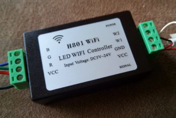
I don’t remember how I found this, but a while ago I ordered one of these modules from china. It’s called H801Wifi, and it’s sold for nine Euros. There’s also an app that controls the lamps from a phone, but I didn’t even bother to test that.

Two years ago I built a project that runs by the name of IRlicht (I was sure that I published it at that time — seems that I still have to). It does almost the same: it controls the brightness of LED strips. My own projekt does that on four channels: RGBW. Red, green, blue and white. This device controls RGBWW, meaning that it would be possible to attach for example a warm and a cold white strip, in addition to the RGB one.

My DIY-one is controlled via infrared remote control. This module is driven by an ESP8266, so it works in a WiFi network. I’m fooling around with a firmware for small WiFi-devices for a while, that communicates with the MQTT protocol. This module would be a great platform to use it on. It’s just questionable if it’s possible to get my own firmware to this off-the-shelf-device…

Turns out: yes. It’s possible. :-)

Flash-jumper set, connected to serial

Flash-jumper set, connected to serial

I’m not the first one to try that. Andreas Hƶlldorfer did it, and he wrote about it. I didn’t expect it to be that simple. Almost disappointing… ;-)

On the PCB — and thanks to great photos in most of the offering shops I knew that ahead of the purchase — is a well labeled serial interface. And right next to that is a connector that literally wants a jumper to be set on it. When the jumper is set, it’s possible to flash a new firmware over the serial interface. Right from the Arduino IDE. I just connected my USB-serial-interface between computer and the module (without connecting external power to it, I don’t know if that would have damaged anything), and I configured the module in the IDE like this:

  • Board: “Generic ESP8266 Module”
  • Flash Size: “1M (64k SPIFFS)
  • Upload Speed: “1152200”

After connecting RX and TX in the right way, I was able to upload my firmware.

I mentioned to have an almost fully working firmware for my use, based on the excellent Homie for ESP8266 framework. ‘Almost’, because till now it just does RGB, not RGBWW. But the only thing I had to adapt for using RGB on this device instead of my usual hardware were the IO-Pins. The “Generic ESP8266 Module” header file doesn’t know any readable names for the pins, so I had to use the numbers. Andreas Hƶlldorfer already found out the mapping, though it seems that he’s got a different revision of the hardware. This worked for me:

Pin Function
15 Output red
13 Output green
12 Output blue
14 Output white 1
4 Output white 2
1 Internal LED green / Signal
5 Internal LED red / Power

I like that, after initial flashing the OTA-Update (Over The Air) works. This way, I could already close the box again. All further updates will be uploaded over the air. :-D

Most pins are in use

Most pins are in use

The ESP8266 is an interesting chip, I mentioned it here several times (sorry: mostly german). In a short description, it’s a freely programmable microcontroller. Compared to Arduino & Co., it’s a real number cruncher. The ESP is faster, has more memory, and the best thing: it has builtin WiFi. You’ll find more information all over the network, a basic overview is contained in Wikipedia.

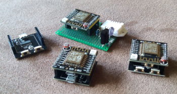
I tested several boards when playing with this chip. Today, I want to describe one that goes with the name Witty Cloud.

Basically, it’s a board with an ESP-12-F, a USB connector that delivers power, a little pushbutton, a LDR (Photoresistor) and a RGB-LED. So there’s plenty of hardware to play with. When you buy the module, you receive a stack of two PCBs. The lower one has a second USB connector, which is equipped with a serial converter. So it’s not only used as a power source, but also as a programming and debugging interface. Furthermore, there’s a reset- and a flash-button on the lower board. After programming, you just need the upper board, and you can even send newer firmware versions to it over the air (OTA).

The  lower board is only used for programming

The lower board is only used for programming

Stacked like this, the module costs less than three Euro, you just need a USB cord and a compiler to start programming. I suggest using the Arduino IDE, it’s very easy to use, even for beginners. After installation of the ESP8266 extensions, it’s best to select WeMos D1-Mini in the board manager, this way everything works fine.

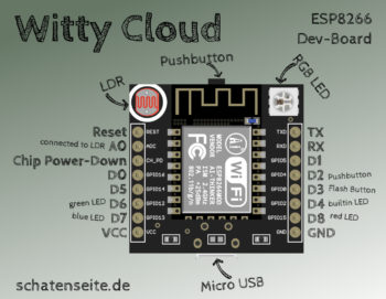
Unfortunately, it’s not easy to find proper documentation for the Witty. So i scribbled the picture above, at first to have some kind of reminder for myself. So the pin labeled GPIO13 is connected to the blue channel of the RGB-LED, in the Arduino environment it’s called D7.

Label Pin (Arduino) Purpose
REST Reset
ADC A0 Analog input, connected to LDR
CH_PD Chip Power-Down
GPIO16 D0 GPIO, freely usable
GPIO14 D5 GPIO, freely usable
GPIO12 D6 GPIO, green channel of RGB-LED
GPIO13 D7 GPIO, blue channel of RGB-LED
VCC +5V power
TXD TX Serial interface
RXD RX Serial interface
GPIO5 D1 GPIO, freely usable
GPIO4 D2 GPIO, connected to pushbutton
GPIO0 D3 GPIO, connected to flash-button, not really freely usable
GPIO2 D4 GPIO, connected to blue LED on the ESP-Module
GPIO15 D8 GPIO, red channel of RGB-LED
GND Ground

I would be highly interested in a circuit of the board, and if you have any corrections or suggestions: just let me know.

Mein Fazit: ein echt interessantes Board. Wer mehr GPIO braucht sucht vielleicht lieber nach einem NodeMCU, wer sowieso einen LDR oder eine RGB-LED braucht sollte zugreifen. Ich habe mittlerweile einige davon hier, und eine Firmware mit der ich die Dinger hier im Haus verteilen mƶchte ist auch fast fertig.

Oh, das Bild habe ich Ć¼brigens mit einer Grafik aus diesem Projekt gemacht, das ist die Witty Cloud fĆ¼r Fritzing.

The completed controller

The completed controller

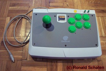
This is a project from 2004. I had it covered extensively on my old homepage, including some more pictures, circuit diagrams and a description on how I analyzed the keyboard controller.

Nowadays, PCs don’t have a PS/2-interface anymore. I’d base a project like this on microcontrollers if I would do it again, and interface the computer via USB. So I leave the details in the past and give just a short description of the project.

At that time, I was interested in MAME, the Multi Arcade Machine Emulator. You can play all the old arcade game classics with that. A PC keyboard is not the ideal interface for thos games, so I started building my own controllers.

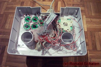
Ratsnest

Ratsnest

Originally, the joysticks were sold to fit a Sega Dreamcast console. I threw out the electronics and implanted a PC keyboard controller instead. I had to find out the keyboard matrix layout and interface all the joysticks microswitches to the right contacts on the controller board. Not too complicated.

The second player’s contacts were connected to a second unit with an old serial cable. Additionally, I built a Y-adapter for the PS/2-interface, so I was able to control the PC outside of MAME.

The result surely wasn’t a pretty build, but: it worked. :-D

Nowadays, I don’t have a PC with a PS/2-interface anymore. I already dismantled one of the joysticks and built something else. But that’s a different story…

See also…

I mentioned this project in an article (german only) on this blog, it dates back from November 2012. Somehow I never showed it, I don’t really know why.

Those who read this blog for a while know that I have a deep faible for computer keyboards. You don’t get the full picture from my english language articles, but in german you can find many keyboard related articles on this site.

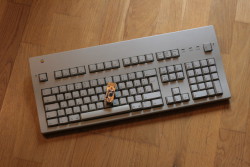
Amongst others, my collection contains two vintage Apple keyboards. There’s a — really not too shabby — Apple Extended Keyboard II, which was built between 1990 and 1994. Many enthusiasts claim that this is the best keyboard ever produced by Apple, partly of course because of it’s mechanical nature with the Alps switches.

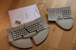
Even more original — and in my eyes it’s a typical Apple product — is the Apple Adjustable Keyboard, 1993 vintage. Typical Apple? As I said, in my eyes: it was expensive for its time, and above all the visual appearance of the product is more important than functionality. Even though there are arrow-keys on the main keyboard, I personally wouldn’t want to miss function- and navigation-keys (Home, End, PgUp, PgDown). And if you connect the additional keypad, you really have to have long arms to reach your mouse… :-/

However, I wanted to give both a try. And since I don’t have access to a computer with ADB interface — Apple killed it in 1999 — I needed a converter. You can buy this stuff, but you don’t have to.

On geekhack.org, there’s a japanese developer called hasu, who is tmk on Github. He created and published the TMK Keyboard Firmware Collection. That’s a firmware that can be run on several AVR-based platforms, notably the Teensy 2.0 which is well known in keyboard communities. The firmware is able to ‘talk’ several different keyboard protocols. Of course, USB in one direction, to be connected to any modern computer. In the other direction there are protocols like PS/2, Sun or Apple Desktop Bus. The custom firmware is loaded with features even expensive modern high end boards fail to deliver. It’s possible to program macros, use media keys or control the mouse pointer with the keyboard.

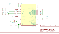
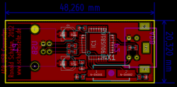
Unfortunately, I didn’t have a Teensy at home. But I had all the parts to build something compatible, and all the tools to etch a fitting PCB. So I fired up KiCad and designed a minimal circuit, from that it wasn’t too difficult to create a PCB layout:

(The KiCad files need a bit of a workover, so I won’t publish them here. But it should be easy to recreate the circuit following the two screenshots.)

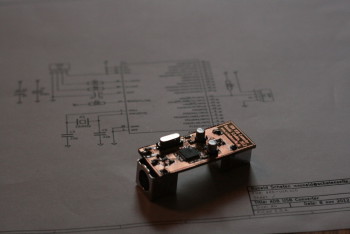
ADB USB Converter

ADB USB Converter

The finished converter measures in at 2x5cm, that’s really tiny. But the important thing is: it works!

I could probably use the ADB mouse with an off-the-shelf converter. But honestly: even a hardcore fanboy would prefer a modern pointing device without the ball in it. That is: a while ago I had the opportunity to play a bit with System 7.5 (the Apple operating system from the same era as the two keyboards), and I have to confess that the Adjustable Keyboard did its part for the authentic user experience… :-D

I took this article from my old CMS in 2015, it wasn’t in the blog until then.
Breadboard in action

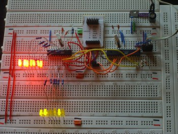
Breadboard in action

I haven’t done many microcontroller-projects till now, but more than one of the few projects I did involved controlling LEDs by pulse width modulation (PWM). Doing this for one or more LEDs is a stressful task for a little microcontroller, but if you want to do some other more or less complicated things while keeping LEDs at certain brightnesses is likely to ruin the timings that are used in the PWM. Not to talk about the program code, which gets more and more unreadable if you try to do several different things ‘at the same time’.

For my next project I need to fade some LEDs again, so I was looking for an easier way to do it. The plans include reading from memory cards, talking to real time clocks and displaying text on an LCD, so I’m almost sure that I won’t be able to reliably control the five channels I’m going to use.

The first plan was to use a ready-made chip. I looked around and the best thing I could find was one made by Philips (PCA something, I forgot the number) that can be controlled via I2C-bus. That part is able to control eight LEDs, but apart from ‘on’ and ‘off’ you can set the LEDs only to two different brightnesses. Those are variable, nevertheless, but it would be impossible to light one LED at 20%, one at 50% and one at 80%. Another drawback is that it is SMD-only, and my soldering-skills don’t including working with stuff that small.

So the Idea was to set up a separate controller for LED-fading, that can be externally controlled, ideally via I2C-bus since I intend to use several other devices in my next project that can make use of the bus. So I set up an ATtiny2313 on my breadboard, clocked it with an external 20MHz-crystal and we tried to control as many LEDs as possible…

Pulse width modulation

Controlling the brightness of LEDs by PWM is a common technique, I used it myself in several projects.

The old way

Till now I used to switch on all LEDs that should light up at a level greater than zero, waited till the first of the LEDs has to be switched off, switched it off, waited for the next one and so on. After a certain time all LEDs are switched off, and I start again.

I try to visualize that with a little picture:

In this example, a full cycle of the PWM would need 50 units of time. The first LED is switched on the full time (100%), the second for 40 of the 50 units (80%), the third one for ten (20%) and the fifth one for 30 units (60%). The fourth LED is off (0%). We see that after 50 units of time the modulation starts again.

The drawback of this technique is, that it’s slow. And for each additional channel you try to control, it gets even slower. We tried, but we weren’t able to control more than five LEDs in this way without them to start flickering to a visible amount.

We tried to create an array with all states of the process, so the PWM only would have to loop through the array and set the outputs accordingly. But that didn’t work either, because the used microcontroller doesn’t have enough RAM to store the array.

Thomas’ idea

After some tests that didn’t work out too well, Thomas had a great idea how to implement the PWM. It also works with an array for all states, but the states of the modulation are not displayed for the same time. The first state is displayed for one time-unit, the second one for two time-units, the third one for four and so on. In this way the LEDs are turned on and off more than once per cycle of the PWM, but that doesn’t hurt.

Let’s try to paint a picture again:

So here we see a PWM with eight channels that are able to display up to 64 different brightnesses. Channel one is switched on for one unit of time, channel two for two units and so on. The most interesting thing is on channel five: the LED is switched on for one unit of time, switched off, and switched on again for four units of time.

Lets try a more complicated example — with brighter LEDs, too:

The channels 1 to 8 have the brightnesses 33, 18, 23, 32, 21, 63, 64 and 24.
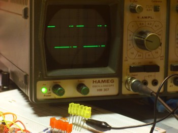
Brightness 75 on the oscilloscope

Brightness 75 on the oscilloscope

The advantage of this technique is that on the one hand you have to save a limited number of states (six states in the example), and the looping through the states is very simple: state n is sent to the output pins, then we wait for 2^(n-1) time units, then the next state is sent.

Each state represents the bit-pattern that has to be sent during one step. In other words: one column out of the above picture at the start of a new time period. So in this example, we have six states: 01010101, 01100110, 01110100, 11100000, 11110110 and 01101001. The first one is displayed for one unit of time, the second one for two units, the third one for four units and so on…

Using this technique has the advantage that adding more channels does almost nothing in terms of system load. The only time that the algorithm has to do actual calculations is when a new value has been delivered and has to be converted into the states. So using this algorithm, it is possible to show different brightnesses on all free pins of the controller. With an ATtiny2313 that means that you can fade 13 different LEDs while still talking I2C to communicate with other devices!

I2C communication

Speaking I2C is no rocket science, but since one has to do a lot of bit-shifting when implementing it, I took a ready-made library.

The one I used is written by Donald R. Blake, he was so kind to put it under GPL and post it to avrfreaks.net. You can find the original post in a thread called ‘8 bit communication between AVR using TWI‘, and some additions in the thread ‘I2C Slave on an ATtiny45‘.

Thanks for the great work, Donald! And for putting it under a free license.

Since his package seems to be only available as a forum-attachment, and I’m not sure for how long that will be, I included it into the tarball of this project.

Usage

You should be able to use this device in the same way you would use any other I2C-slave:

Connecting it

The controller needs to have the following pins connected in the circuit:

  • Pin 1 – Reset – should be connected to VCC with a 10k-resistor
  • Pin 4 and 5 – XTAL1 and XTAL2 – connected to a 20MHz-crystal, using 22p-capacitors against GND
  • Pin 10 – GND – Ground
  • Pin 17 – SDA – I2C-data
  • Pin 19 – SCL – I2C-clock
  • Pin 20 – VCC – 5V

Your I2C-data and -clock lines should be terminated by 4,7k-resistors to pull up the lines. All the other pins can be used to connect LEDs. They are arranged in this way:

  • Pin 2 – PD0 – Channel 0
  • Pin 3 – PD1 – Channel 1
  • Pin 6 – PD2 – Channel 2
  • Pin 7 – PD3 – Channel 3
  • Pin 8 – PD4 – Channel 4
  • Pin 9 – PD5 – Channel 5
  • Pin 11 – PD6 – Channel 6
  • Pin 12 – PB0 – Channel 7
  • Pin 13 – PB1 – Channel 8
  • Pin 14 – PB2 – Channel 9
  • Pin 15 – PB3 – Channel 10
  • Pin 16 – PB4 – Channel 11
  • Pin 18 – PB6 – Channel 12
Talking to it

For my tests I used an ATmega8 as I2C-master with the library written by Peter Fleury. You can find it on http://jump.to/fleury. Thanks to him for putting it online!

The typical send function looks like this:

Examples

I2C-Fader on testboard

Here, you see all LEDs fading at different speeds.


The code running on the I2C-master to generate this pattern looked like this:

Visible PWM

Here you see the signal of one LED fading from 0 to 127. Unfortunately, my oldtimer-oscilloscope doesn’t trigger correctly in the middle part.


This is the code that ran on the I2C-master:

Drawbacks

Till now, the device worked in all situations I tested it in. So far everything is fine.

I guess that, compared to the ready-made off-the-hook-parts that controls LEDs via I2C, this module is a bit slow. I can’t see any flickering in the LEDs since they are still switched very fast (about every 6ms, which would result in a 166Hz flickering — too fast for me).

Thanks!

Once again, special credits go to Thomas Stegemann. He had the great idea for the PWM-algorithm, and I am always astonished by the patience he has to show me how to do anything complicated in a sick language like C…

About the license

My work is licensed under the GNU General Public License (GPL). A copy of the GPL is included in License.txt.

Download

To prevent misunderstandings: this says that it's not a mediaeval toilet.

To prevent misunderstandings: this says that it’s not a mediaeval toilet.

This article wasn’t on the blog in 2011. I took it from my old CMS in 2015.

I built this photo booth for our wedding in summer 2010.

I can’t remember where I got the idea, I guess I saw something similar somewhere on the net. After everything else for the ceremony was set I had some time to spend. And this idea…

Hardware

Manual

Manual

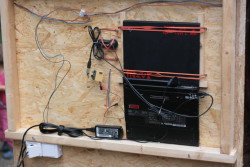
I had most of the needed material at home. Enough wood, a cloth for the curtain, an unused notebook. And a test circuit I built for my USB-projects. I just had to acquire a webcam, a push button like it’s used in moist rooms (how do you call that in english?) and two fluorescent tubes.

Unfortunately, I forgot to take a picture of the entire booth. It was basically a large box made of oriented strand board, about 2.20m high, 1.20m wide and 1m deep. On one side was the entrance, closed by a thick brown curtain. Inside there was a bank, opposed to it the technology.

Visible there were two simple tubes for the light, a rectangular section with a screen, a small round hole with a lens and said moisture-proof switch.

Hidden behind the wall were an IBM Thinkpad T43 along with a power supply, a Logitech Webcam Pro 9000 and some electronics.

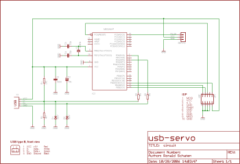
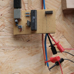
I built this circuit since I didn’t want to make the same USB-interface over and over again on breadboard. It is essentially the same circuit as in my USB LED fader, the USB servo or my Dulcimer Keyboards. An ATmega8 microcontroller and some bird seed for the USB interface, at the other end a pin header to interface all unused pins of the controller on the breadboard.

The box was not built to last forever, so I just had two of the pins connected to terminal cables to the push button.

Software

The circuit is the same as the USB-Servo

The circuit is the same as the USB-Servo

In this project there are two important software components: the photo booth program on the laptop and the firmware on the controller.

The notebook was easy to equip. First I wanted to write a program myself, but after a short search I found something that does exactly what I wanted: Cheese. This is basically a photo booth. You press the space bar, then the program takes four images, at intervals of a few seconds. Simple and perfect.

The microcontroller was not quite as trivial to program, but I already had the solution in the drawer. With a slightly adapted Dulcimer firmware, the circuit behaves just like a simple USB keyboard. I just had to see in the schematic which pins I had to connect to create a space key.

:arrow: In combination with the moisture-proof push button I probably had the only wet room space bar in the world! ;-)
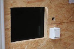
The combination worked perfectly: you go into the box and see the large display. After pressing the button, there were four consecutive pics taken, each with a short countdown.

The pictures end up in a directory and each has the recording time in the file name. That allows to rearrange the pics with a nice one-liner, so the result is a big picture with the full series of four images:

Results

Box of Fools

Box of Fools

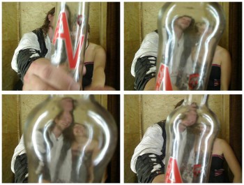
I had assured that I would not put the images into the net, so there is only one unrecognizable example. The names of people and the original contents of the bottle are withheld. :-)

The quality has really surprised me. The camera makes really sharp and detailed images, and the fluorescent lights illuminated everything pretty evenly.

The box was used at the wedding-eve party and at the actual wedding. From the eve we’ve got more than 500 images, from the wedding even more than 800. Almost all the guests have found their way into the box, most of them repeatedly. And in packs: on some pictures we see at least seven people at once…

The curtain has proven to be a terrific feature. On many of the pictures you can see that the people did not expect that we can see the pictures lateron… ;-)

We are happy about each image. By means of that box, and above all the spontaneity of our guests, we have truly unique memories of one of the best days of our lives. Thanks again to all who joined us!

I didn’t have this article on my blog in 2009, it came over from my old CMS in 2015.

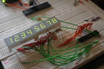
Test circuit on breadboard

Test circuit on breadboard

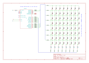
This project turns an AVR ATmega8 microcontroller into a LED controller for a matrix of 8×8 LEDs. The controller is acting as I2C-slave, so you can control the patterns to display via this bus (also known as TWI, Two Wire Interface).

Purpose

For my next project, I need to display number values on seven-segment-displays. I bought a bunch of 4-digit-displays a while ago, now I’m going to put them to a use. They are built with four digits in one case, and 12 pins on the underside. Eight of them are the cathodes of the segments (seven segments plus dot), four are the anodes. One for each digit.

You can imagine these modules as a matrix of four times eight LEDs, as can be seen in the included circuit. I use two of these, so I have a matrix of eight times eight LEDs.

The rows and columns of this matrix are connected to the microcontroller, so it can power them row by row. This has two advantages: at first a maximum of eight LEDs is powered at a time, so power consumption is lowered. And at second you need only 16 pins of the controller to address a total of 64 LEDs.

Driving the LEDs in this way makes them flicker a bit, but the controller is fast enough to keep the flickering way above the level you would be able to recognize.

I could have connected my display modules directly to the main controller of my next project, but I don’t have enough free pins on that. As a further benefit, multiplexing the LEDs on a second controller makes the main program easier to write, since I don’t have to mind the timing. So the solution is to use a cheap ATmega8 as LED driver and use the I2C-bus to tell it what to display.

I2C communication

The ATmega8 has a built-in hardware I2C-interface, so it doesn’t take very much code to use it. Nevertheless, I used a little library that Uwe Grosse-Wortmann (uwegw) published on roboternetz.de. I only reformatted it a bit to make the code resemble my style. It is well commented, but the comments are in german. Since only one global array, one init-function and an interrupt service routine are used, it shouldn’t be too hard for english-speaking people to figure out how it is used.

Usage

On the other end of the communication, I used the excellent Procyon AVRlib written by Pascal Stang. You can find it here.

The Circuit

The Circuit

Note: the buffer doesn’t contain any numbers that should be displayed on 7segment-displays. At least not in this example. It only holds bit-patterns.

Displaying numbers

If you solder 7segment displays to the unit and intend to display numbers or characters on it, you need to define them on the master-side of the bus. I didn’t include the definitions in this library because I want the master to have the full flexibility of displaying whatever it wants to, even if it are no numbers.

However, if you are going to use 7segment displays, definition of the numbers still depends on how you soldered them to the controller. I don’t know if the pin-outs are commonly standardized.

To give an example of how you would implement this, here is a fragment of code that defines hexadecimal numbers for usage on my displays:

Drawbacks

Till now, the device worked in all situations I tested it in. So far everything is fine.

Thanks!

I’d like to thank the authors of the libraries I used: Uwe Grosse-Wortmann (uwegw) for the I2C-slave and Pascal Stang for the Procyon AVRlib.

About the license

My work is licensed under the GNU General Public License (GPL). A copy of the GPL is included in License.txt.

Download