Dungeons & Dragons, the mother of all role playing games, uses alignment charts to classify characters along the lines of “lawful” to “chaotic” and “good” to “evil”. Internet-memes classify everything into such charts, from screws to penguins.
Looking at my desktop, a colleague mentioned even screen-setups to be classified this way. My office setup isn’t shown in the chart, but it’s nearest to “chaotic good”.
My home-setup on the other hand is somewhere between “chaotic neutral” and “chaotic evil”. On the left side, I have my notebook’s full HD screen, a big horizontal 4k-Monitor in the center, next to it another full HD in vertical alignment. Works for me.
I see “chaotic evil” as a challenge. Some months ago I read a gloss about the ideal screen setup for programmers. Using “xrandr –listmonitors” I found the internal name of my 4k-screen to be “DP-2-3”. The calculator in the article gave me the following command to rotate the screen’s content by 25°, with a vertical shift of 800 pixels:
One of my biggest – although in recent years very neglected – hobbies is photography. I have always been attracted by the technology and the possibility to explore its limits. Examples of this are the high-speed flash trigger (German only, sorry) I built almost 20 years ago (at that time without a microcontroller (!)), or my darkroom where I pushed the good old Kodak T-Max P 3200 far beyond its limit.
A topic that has always fascinated me is macro photography. With my first SLR – an heirloom from grandpa, a full-manual camera from Revueflex – I had already found a set of extension tubes. Simple ones, with M42 connection, but they got me hooked. After entering the EOS world, I bbought an adapter to use the tubes and lenses on the newer camera, then at some point at a photo fair also an old bellows. And another one.
Boss Monster Depth of Field
One problem when taking macro photos, regardless of which technique you use to go to the extreme, is the lack of depth of field. It’s not uncommon to be dealing with millimeters or even fractions of millimeters. “In my day,” that is, in the analog photo world, you couldn’t do much against that. Nowadays, however, people shoot digitally. So at some point, someone came up with the idea of focus stacking: you don’t just take one picture, you take a whole stack of pictures. Each with the focus in a different plane. You then load this stack into an image editor and tinker with it until you have only the parts that are in focus – and thus an image with a significantly extended depth of field.
Of course, you don’t always want to spend half a day clicking around in Gimp, so resourceful developers have written programs that do the job. There are commercial solutions, but I stuck to open source.
Stack photography with Arduino
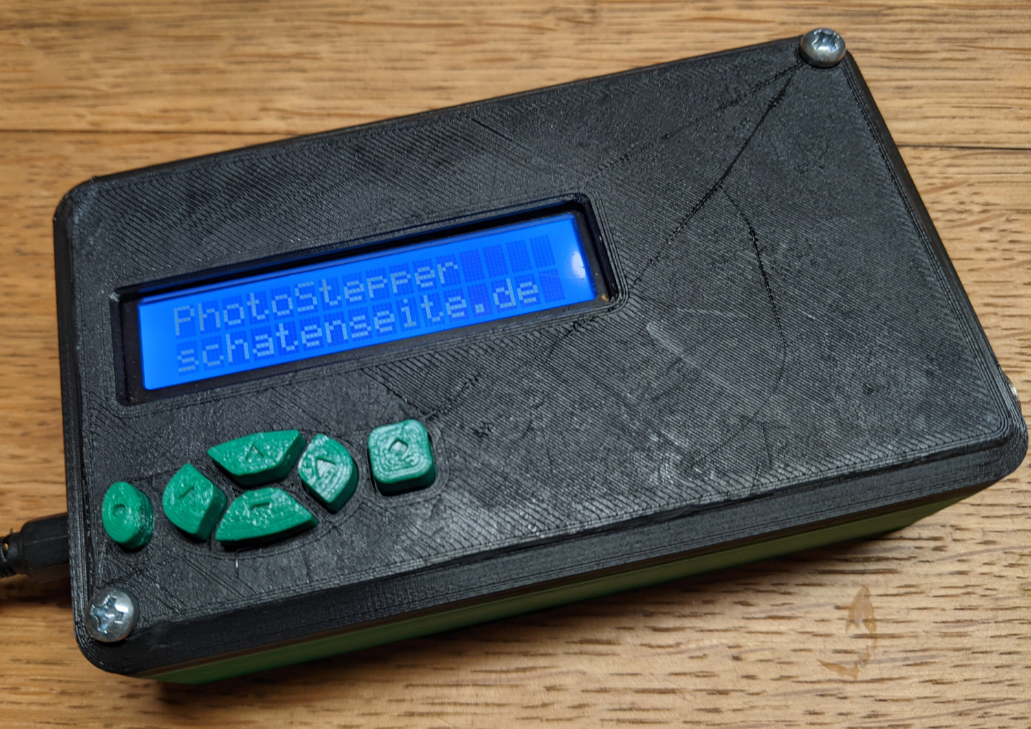
PhotoStepper
What I built is not new. You can buy such devices from various commercial manufacturers, there are also quite a few well documented tinkering projects. Some of them even with practically the same hardware I used. Why did I do it myself anyway? Simply because I wanted to know if I can do it.
So I fished an old Arduino Uno out of the big box of leftovers, plus a LCD keypad shield I bought sometime without really knowing for what. With a stepper motor driver (A4988) and a motor I still had from another project I could try out how it all works together. I could have connected the Arduino directly to the cable release connector of my camera, but that was too exciting for me, considering the 12V supply voltage. So I did that using two optocouplers (PC817).
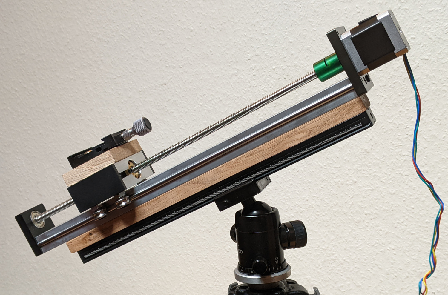
My rig for focus stacking
The prototypical tests worked well, so I printed a case and looked for some suitable mechanics. I was able to get a linear actuator including motor practically as a bargain. Plus a rail for mounting on the tripod and a clamping plate to mount the camera on the slide. And since I am more a carpenter than a mechanic, the connections between the parts are made of rustic oak.
The parts are just like my tripod Arca-Swiss compatible (another term that did not exist “in my time”), so the base plate can stay on the camera and everything is quickly and stably set up.
Photo Session
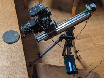
Shooting setup, still without the flash
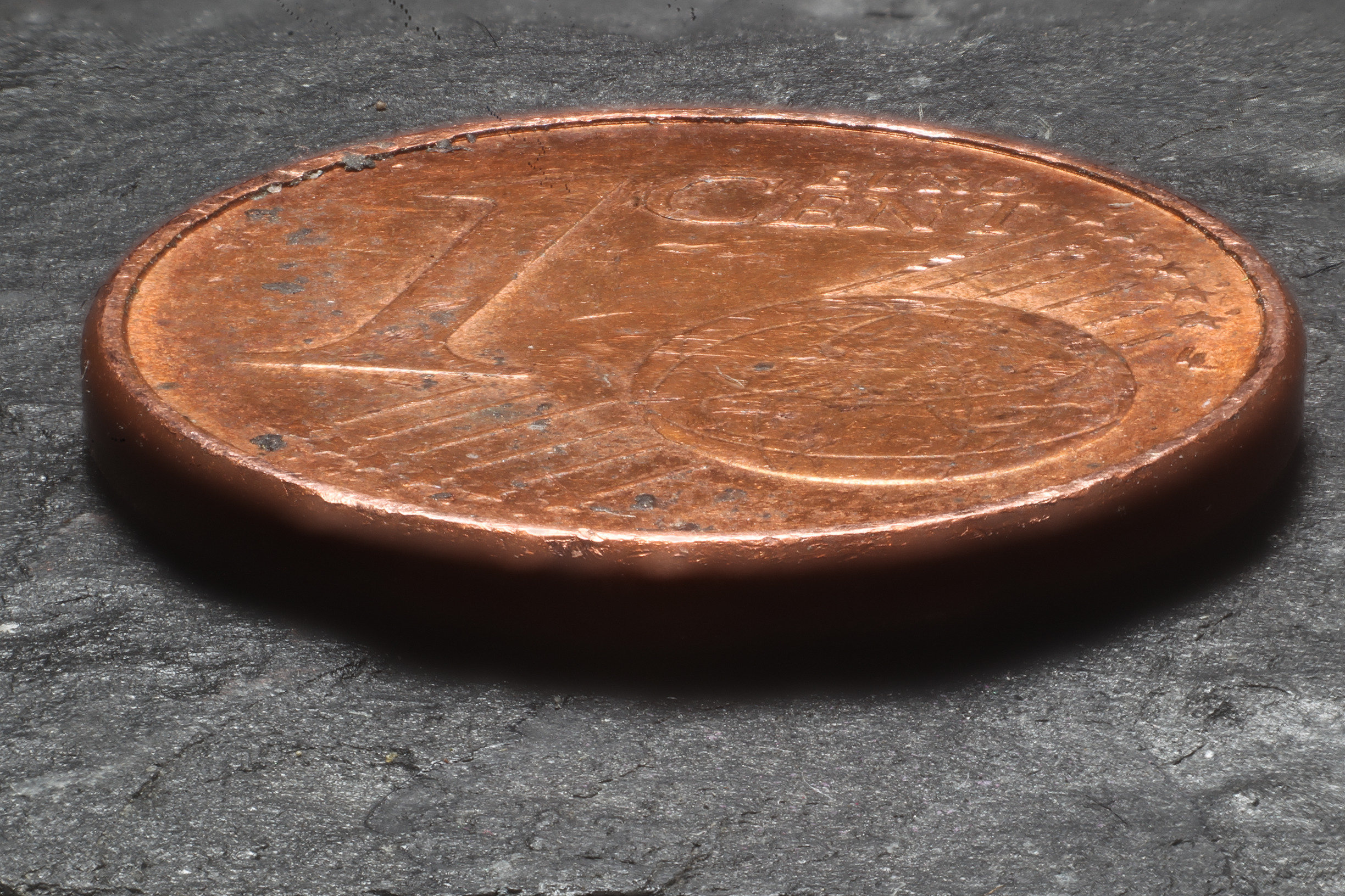
My first subject – a rather dirty Euro-cent – was not original, and the setup is quite crude. Camera with bellows and a 58mm lens from my grandpa’s heritage on the linear drive, a radio triggered flash facing the “model”.
I setup the camera and roughly focused on the coin. Then I set camera and flash to manual mode and selected the right exposure. Up to here nothing unusual.
Then my new device came into play: I moved the camera forward a bit so that the plane of focus was clearly behind the coin. Then I set the device to take 30 pictures, each 1mm apart. So I covered 3cm – enough for the coin, but when you look at the finished shot not enough to stay sharp to the top of the image. Too bad, but it’s just a test.
Cent piece, 30 focus levels
One minute – and a dance of joy behind the camera – later, 30 pictures are in the can.
I drag them over to my computer and edit them with two tools: align_image_stack from the Hugin package makes sure that all images are aligned and resized. The camera moves away from the subject during the shooting, so the subject gets smaller and smaller. This would greatly avert the stacking.
This is done by enfuse from the Enblend project. And it does it amazingly well, I think. Not perfect, though: at the top of the image there are still some artifacts from the processing. But really amazingly good. Especially for a first attempt.
The whole she-bang?
I’ve posted the complete project, including the source code and a description of the electronics.
There you can have a look at everything in detail, and I’m always open for improvements.
Now what…?
To be honest, I don’t really have anything important to photograph with this thing. I have a few ideas, but I was mainly interested in building something like this. Done. Check.
I also know that this is not a groundbreaking invention. I know that there are some modern cameras that already have a focus stacking function built in. If you really need something like that, you will probably go for such a model. My “oldie” from 2009 can only do that with this tool.
Since I just control a stepper motor and the camera with the device, I can imagine to operate it with some kind of a lazy susan. So I could take controlled photographs from all sides. I don’t know yet what I would need that for, but maybe this will develop again sometime in the direction of photogrammetry, so maybe a tool for creating 3D models. Let’s see…
Math lessons in the fifth grade cover — amongst other things, I hope — the binary system.
My favourite fifth-grader asked me for help. Explaining the number-systems is one thing, but you can do more if you’re a geek with a laser cutter. So I built her a binary counter:
Binary counter, laser in wood
The idea for this came from Twitter, I remembered seeing the video a while ago. I couldn’t find any files for this, so I called FreeCAD to the rescue.
I really like the result. And it looks as if the physical model really did help understanding the numbers.
If anybody is interested in building their own version of this: here are the files (planned for 4mm material):
Today I learned a cool new trick, made possible by the Item Preprocessing that is available since Zabbix 3.4. This is not a Zabbix blog, but I consider this so useful and so not-intuitive that I just have to write it down.
For the occasional visitor: Zabbix is an open source enterprise class monitoring solution. I use it not only at work, but also at home — not only to monitor the meat on my BBQ.
In my opinion, Zabbix is really great when it comes to anything that can be expressed in numerics. It can also handle string data, but having had minor problems with that I try to avoid strings whenever it is possible. States can be expressed numerically and stored in integer values, using value mapping it is possible to show the states in a meaningful way.
Today I came across a problem that I wasn’t able to implement at first. A web service told me the state of an application, which could be either RUNNING, STOPPING or STOPPED. It’s easy to create a string-item to handle this, and to implement a trigger that notifies if the service is STOPPED. However, in this case I had to create a trigger that tells if the service is in the state STOPPING for more than a certain time, indicating that it might have a problem shutting down. I couldn’t find a solution to this, since the trigger function str("STOPPING",15m) would trigger if at least one of the values during the last 15 minutes was “STOPPING”.
Item Preprocessing to the rescue!
Three steps
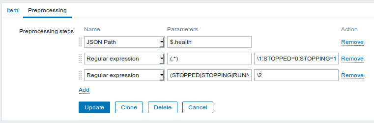
Zabbix 3.4 brought a feature called Item Preprocessing. A value can be fetched, and before it gets stored it can be dissected or converted in several ways. One of these is, to apply regular expressions to the fetched value, in a “find and replace” kind of way.
It turned out that I needed a fairly complex expression, but in the end I was able to convert the states from the webservice to simple integers. Searching the web, i found something about “conditional replacement”, and using this great online regex tester I was able to come up with this beauty:
1
(STOPPED|STOPPING|RUNNING)(?=.*:\1=(\d))
Using this, I can convert the string that is extracted from the web service’s output using a JSON path in two further steps:
First, attach a “dictionary” to the value: replace the full value (.*) with with itself, followed by the replacement values: \1:STOPPED=0:STOPPING=1:RUNNING=2.
Then, replace the regex (STOPPED|STOPPING|RUNNING)(?=.*:\1=(\d)) by the value of the second capturing group \2.
In this way the item can be configured as an unsigned integer, since there are only the numbers 0, 1 or 2 that have to be stored. And I can apply the usual trigger-function-magic to notify if the value is 1 for a certain length of time. Added benefit: I can use the graph view of this item to see if there were any deviations from the wanted “RUNNING” state, when they occured and how long they lasted.
Better ideas?
I’m pretty enthusiastic about this way of processing the values. But I’m also very interested in opinions: is there a better way to deal with this problem? Something obvious that I haven’t seen?
Unfortunately, this project is still work in progress. But I want to tell of the first test run anyways. The electronics didn’t do exactly as it was supposed, but you see where this is going.
About two years ago, I built a prototype of a BBQ thermometer, which I showed here (german only, sorry). It really was just a quick hack, not really intended for repeated usage. I have learned a lot since then, and now I want to build something like that, but this time as a ‘real project’.
Being able to measure core temperatures of multiple pieces of meat, I didn’t have to think about the project’s name for long: Multimeater!
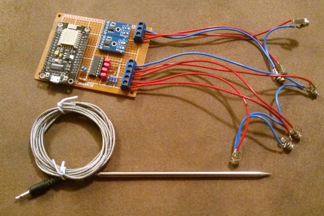
The Hardware
Like some of my last projects, this is based on an ESP8266-module, with software developed in the Arduino IDE. So it already runs WiFi. My firmware is — as in some of my other recent projects — based on the Homie-framework. It sends collected values via MQTT to my broker, from there they are delivered to Zabbix. Values are measured with two high temperature sensors each connected to a MAX6675, and four common meat thermometers on a MCP3208.
Six temperatures? Yes. The plan is, to acquire the inner temperature of the pit on two positions. Under certain circumstances, these temperatures can be too high for the meat sensors. So I take two separate sensors for this, one on each end of the pit (which is a bit lengthy on a smoker, so there really is a relevant bit of a temperature drop in between). And with four meat thermometers I can monitor core temperatures of — you guessed it — up to four pieces of meat.
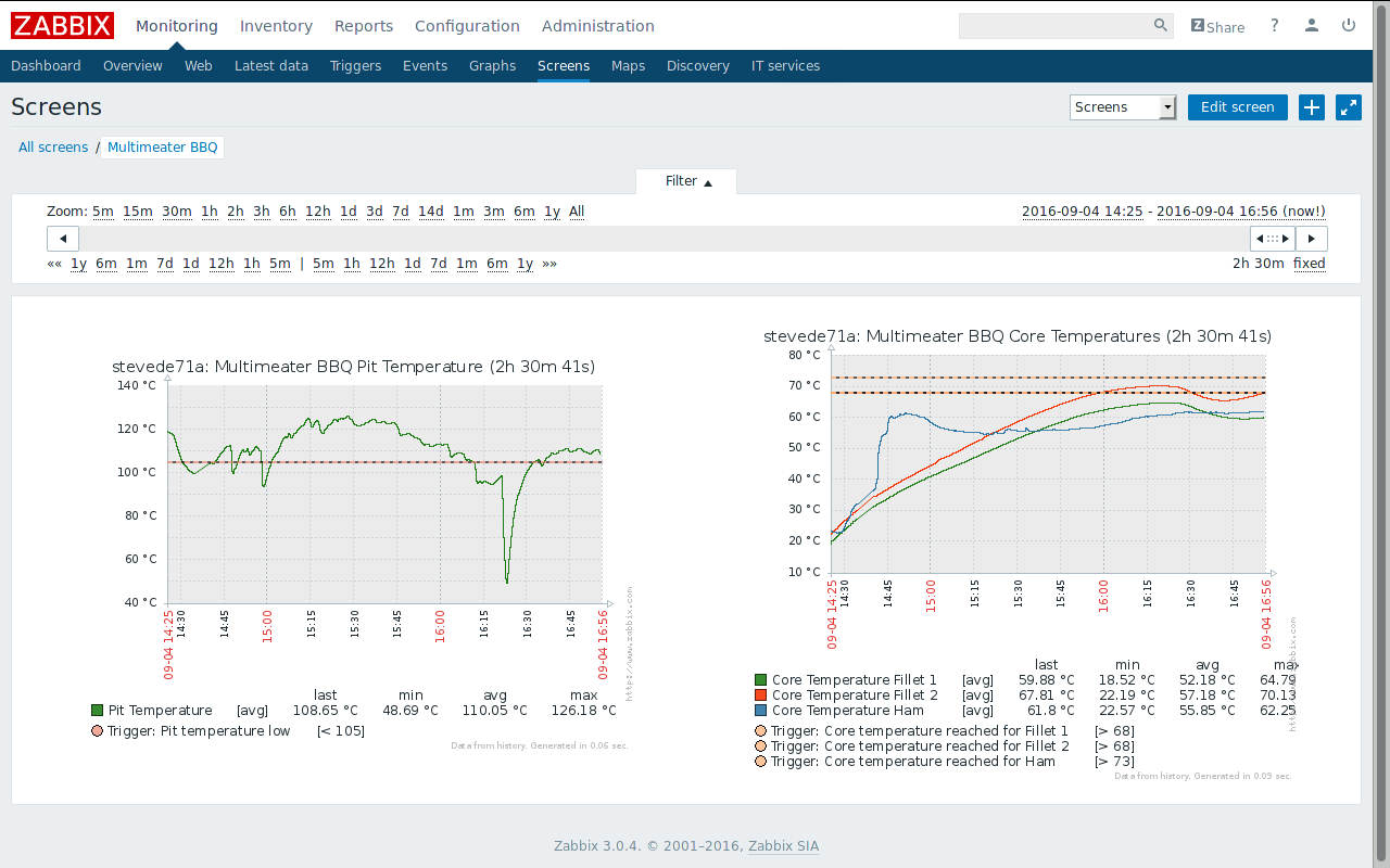
Zabbix is usually used as a monitoring software for server systems. But it doesn’t just work in enterprise environments, I am collecting some… let’s say unusual values at home.
In this case, I just used it to see graphs of the temperatures. But if I’m really starting to smoke me a pulled pork over night, I can tell Zabbix to wake me up if temperatures are out of a predefined range.
As mentioned, today’s run was just a test. And of course, several things didn’t work out as they were planned. I had a problem with the high temperature measurements in the pit. Those values turned out to be completely useless. But since I just bought three pieces of meat for today, I was able to use the fourth meat sensor for the pit temperature. Then I misplaced the sensor in my piece of ham, so the graph looks a bit strange. And to top all this off, heavy rain poured down during the test. Currently, there is no roof over the smoker, so that didn’t make it easier, either.
All in all, everything looked quite promising. I keep bringing this forward, and as soon as I really get it to work I’m going to publish it here, of course with circuit and firmware.
Oh, and since I’m sure that I’ll get that question: technical problems aside, I had some awesome pieces of meat from this test. Everybody really enjoyed it.
Normally, it would make much more sense to publish a project when it is done. In this case, I was sure that I had done exactly that. It’s just a few days since I realized that I didn’t. Funny, it’s been exactly three days before I replaced the project by something else. However, even if it’s a bit late, I’ll deliver…
In early 2014, we renovated our living room. One wall got a rocky structure, and I thought that was the perfect place for a grazing light from above. This screamed for LED-strips. Fooling around with my daughters, I mentioned a plan of installing a pink light. The plan was to go with warm-white, but they insisted on a pink light… two against one, I was in defense position.
Theoretically, a simple RGB-strip can be made to give white light. Practically, most times that’s a really ugly tone of white. So I installed a warm-white strip next to the RGB one. The controller that was delivered with the RGB-strip wasn’t able to power this combination, so I needed a RGBW controller. I couldn’t find an affordable one, so I had to build it myself.
That’s how it works
If I remember correctly, that was my first Arduino project. And it was surprisingly easy to do. I built a first prototype with an Arduino Uno, and with the great infrared receiver library by Ken Shirriff I was able to control a RGB and a white LED after just two hours. Using my trusty Logitech Harmony, which also controls the rest of my media system.
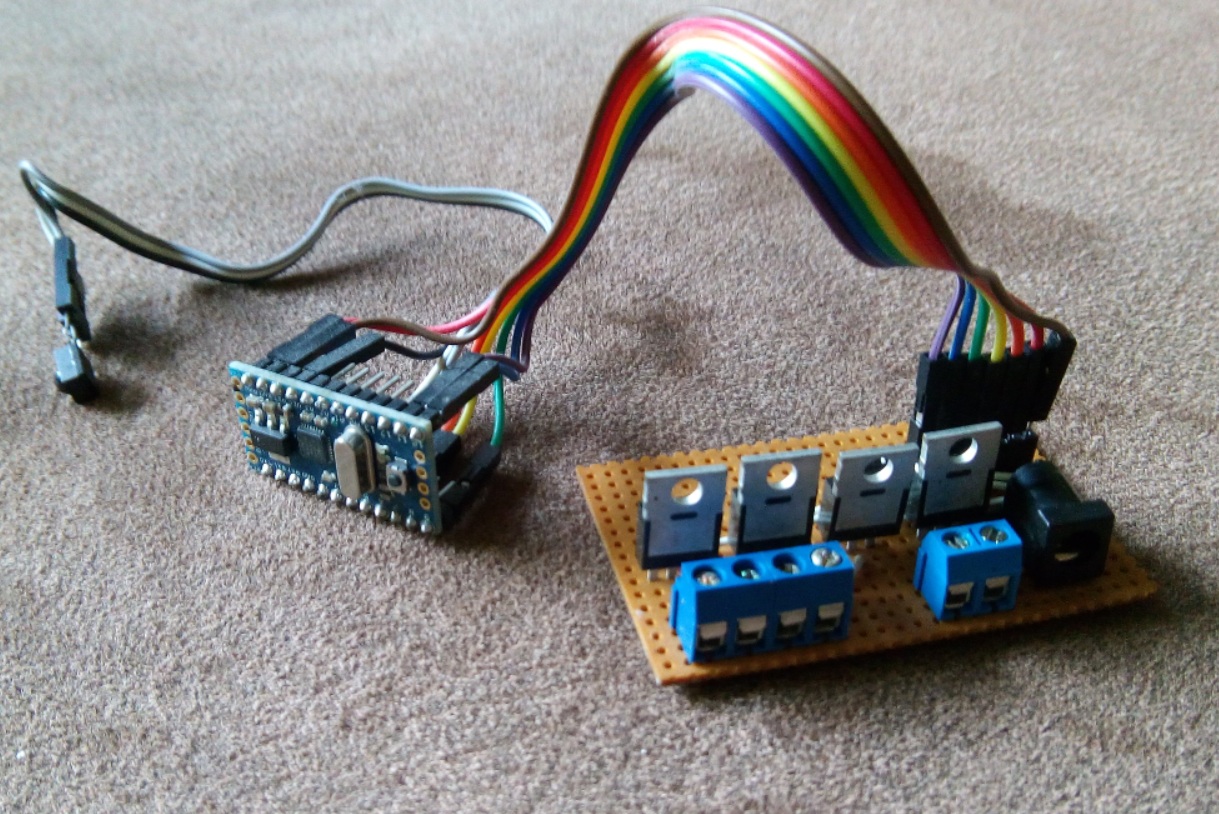
The second prototype I built using MOSFETs, to test how I would be able to control the LED-strips with an Arduino. They are powered with 12V, after all.
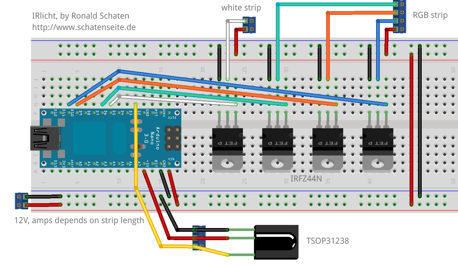
The final build is pictured on the photo above: an Arduino Pro Mini (the one without USB interface), and a simple PCB that is wired for controlling the strips. There’s an infrared receiver wired to the Arduino. Initially, that was a TSOP31238, but I fried it just before finishing the project by wiring it wrong. Wanting to get this done, I gutted an old DVD player. I don’t have the slightest idea what type of receiver this is, but it works.
That means: it did work. Almost exactly for two years. Till today. Now it’s obsolete — as I said. Sources and documentation go by the name of IRlicht, I published today.
Oh, and if that’s of anybodys concern: until today, the lamp was used almost only in the white mode. The colors — and especially the color changing modes — were used only for testing and for showing how it works. It was used rarely enough that I had to look up the used keys in the source code…
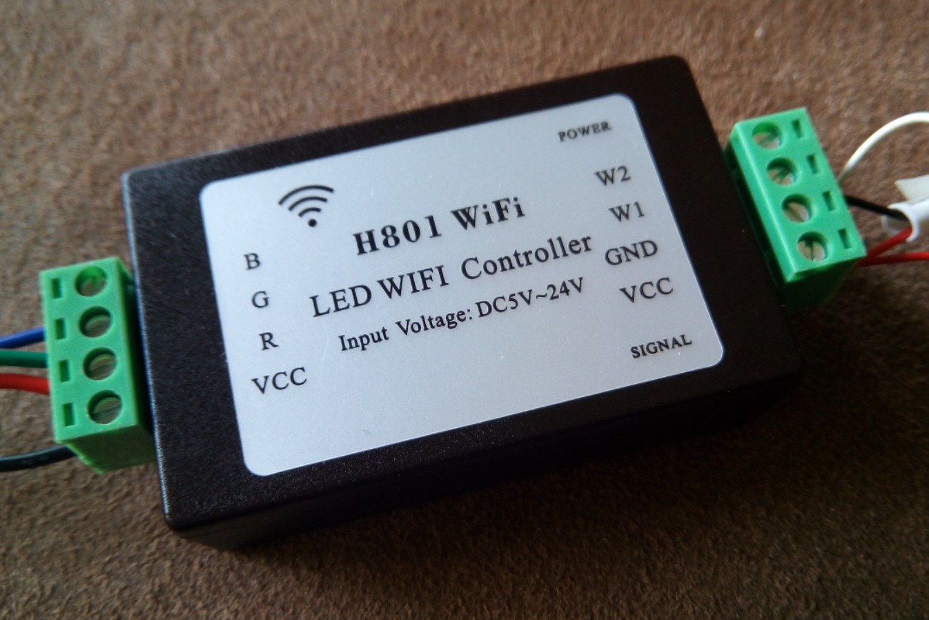
I don’t remember how I found this, but a while ago I ordered one of these modules from china. It’s called H801Wifi, and it’s sold for nine Euros. There’s also an app that controls the lamps from a phone, but I didn’t even bother to test that.
Two years ago I built a project that runs by the name of IRlicht (I was sure that I published it at that time — seems that I still have to). It does almost the same: it controls the brightness of LED strips. My own projekt does that on four channels: RGBW. Red, green, blue and white. This device controls RGBWW, meaning that it would be possible to attach for example a warm and a cold white strip, in addition to the RGB one.
My DIY-one is controlled via infrared remote control. This module is driven by an ESP8266, so it works in a WiFi network. I’m fooling around with a firmware for small WiFi-devices for a while, that communicates with the MQTT protocol. This module would be a great platform to use it on. It’s just questionable if it’s possible to get my own firmware to this off-the-shelf-device…
Turns out: yes. It’s possible.
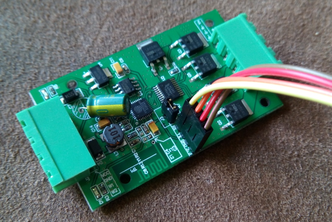
Flash-jumper set, connected to serial
I’m not the first one to try that. Andreas Hölldorfer did it, and he wrote about it. I didn’t expect it to be that simple. Almost disappointing…
On the PCB — and thanks to great photos in most of the offering shops I knew that ahead of the purchase — is a well labeled serial interface. And right next to that is a connector that literally wants a jumper to be set on it. When the jumper is set, it’s possible to flash a new firmware over the serial interface. Right from the Arduino IDE. I just connected my USB-serial-interface between computer and the module (without connecting external power to it, I don’t know if that would have damaged anything), and I configured the module in the IDE like this:
Board: “Generic ESP8266 Module”
Flash Size: “1M (64k SPIFFS)
Upload Speed: “1152200”
After connecting RX and TX in the right way, I was able to upload my firmware.
I mentioned to have an almost fully working firmware for my use, based on the excellent Homie for ESP8266 framework. ‘Almost’, because till now it just does RGB, not RGBWW. But the only thing I had to adapt for using RGB on this device instead of my usual hardware were the IO-Pins. The “Generic ESP8266 Module” header file doesn’t know any readable names for the pins, so I had to use the numbers. Andreas Hölldorfer already found out the mapping, though it seems that he’s got a different revision of the hardware. This worked for me:
Pin
Function
15
Output red
13
Output green
12
Output blue
14
Output white 1
4
Output white 2
1
Internal LED green / Signal
5
Internal LED red / Power
I like that, after initial flashing the OTA-Update (Over The Air) works. This way, I could already close the box again. All further updates will be uploaded over the air.
The ESP8266 is an interesting chip, I mentioned it here several times (sorry: mostly german). In a short description, it’s a freely programmable microcontroller. Compared to Arduino & Co., it’s a real number cruncher. The ESP is faster, has more memory, and the best thing: it has builtin WiFi. You’ll find more information all over the network, a basic overview is contained in Wikipedia.
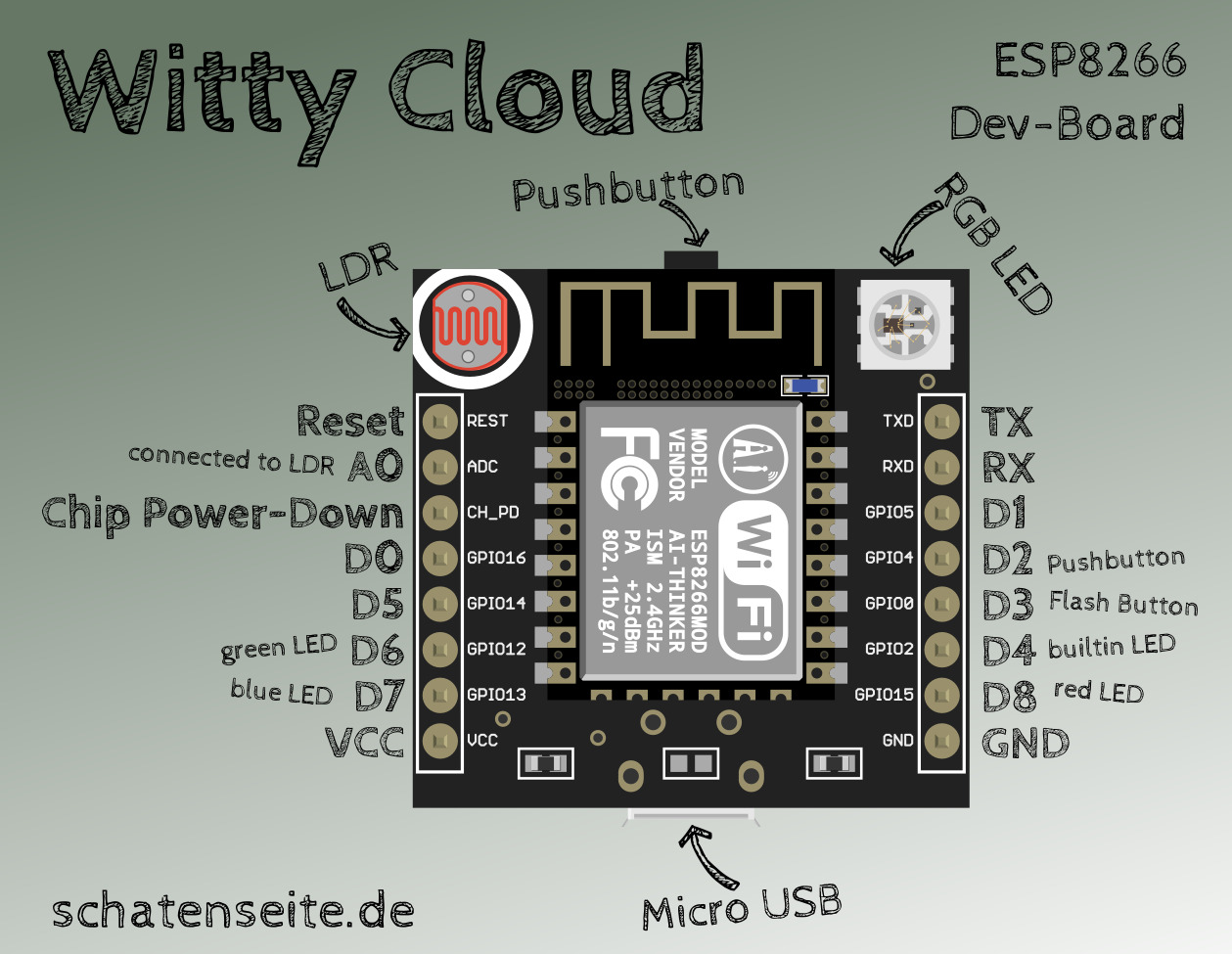
I tested several boards when playing with this chip. Today, I want to describe one that goes with the name Witty Cloud.
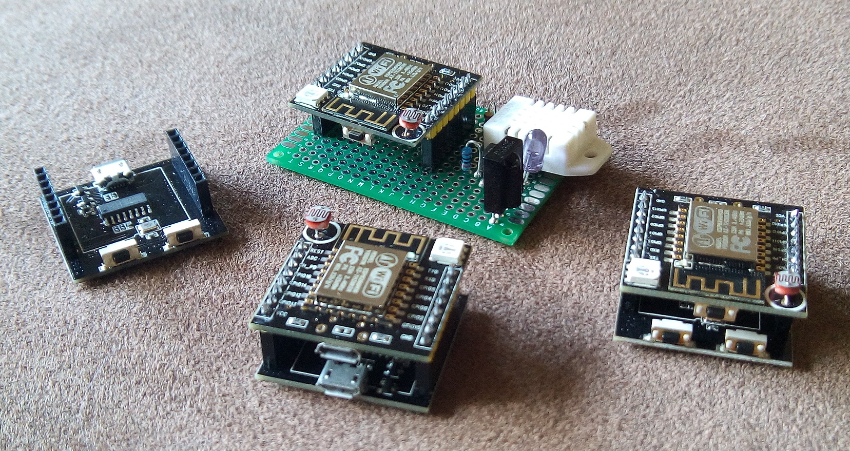
Basically, it’s a board with an ESP-12-F, a USB connector that delivers power, a little pushbutton, a LDR (Photoresistor) and a RGB-LED. So there’s plenty of hardware to play with. When you buy the module, you receive a stack of two PCBs. The lower one has a second USB connector, which is equipped with a serial converter. So it’s not only used as a power source, but also as a programming and debugging interface. Furthermore, there’s a reset- and a flash-button on the lower board. After programming, you just need the upper board, and you can even send newer firmware versions to it over the air (OTA).
The lower board is only used for programming
Stacked like this, the module costs less than three Euro, you just need a USB cord and a compiler to start programming. I suggest using the Arduino IDE, it’s very easy to use, even for beginners. After installation of the ESP8266 extensions, it’s best to select WeMos D1-Mini in the board manager, this way everything works fine.
Unfortunately, it’s not easy to find proper documentation for the Witty. So i scribbled the picture above, at first to have some kind of reminder for myself. So the pin labeled GPIO13 is connected to the blue channel of the RGB-LED, in the Arduino environment it’s called D7.
Label
Pin (Arduino)
Purpose
REST
—
Reset
ADC
A0
Analog input, connected to LDR
CH_PD
—
Chip Power-Down
GPIO16
D0
GPIO, freely usable
GPIO14
D5
GPIO, freely usable
GPIO12
D6
GPIO, green channel of RGB-LED
GPIO13
D7
GPIO, blue channel of RGB-LED
VCC
—
+5V power
TXD
TX
Serial interface
RXD
RX
Serial interface
GPIO5
D1
GPIO, freely usable
GPIO4
D2
GPIO, connected to pushbutton
GPIO0
D3
GPIO, connected to flash-button, not really freely usable
GPIO2
D4
GPIO, connected to blue LED on the ESP-Module
GPIO15
D8
GPIO, red channel of RGB-LED
GND
—
Ground
I would be highly interested in a circuit of the board, and if you have any corrections or suggestions: just let me know.
Mein Fazit: ein echt interessantes Board. Wer mehr GPIO braucht sucht vielleicht lieber nach einem NodeMCU, wer sowieso einen LDR oder eine RGB-LED braucht sollte zugreifen. Ich habe mittlerweile einige davon hier, und eine Firmware mit der ich die Dinger hier im Haus verteilen möchte ist auch fast fertig.
Oh, das Bild habe ich übrigens mit einer Grafik aus diesem Projekt gemacht, das ist die Witty Cloud für Fritzing.
This is a project from 2004. I had it covered extensively on my old homepage, including some more pictures, circuit diagrams and a description on how I analyzed the keyboard controller.
Nowadays, PCs don’t have a PS/2-interface anymore. I’d base a project like this on microcontrollers if I would do it again, and interface the computer via USB. So I leave the details in the past and give just a short description of the project.
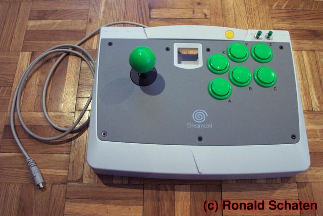
At that time, I was interested in MAME, the Multi Arcade Machine Emulator. You can play all the old arcade game classics with that. A PC keyboard is not the ideal interface for thos games, so I started building my own controllers.
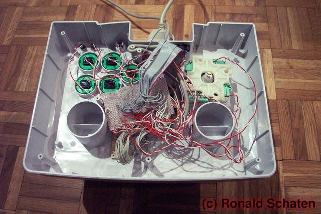
Ratsnest
Originally, the joysticks were sold to fit a Sega Dreamcast console. I threw out the electronics and implanted a PC keyboard controller instead. I had to find out the keyboard matrix layout and interface all the joysticks microswitches to the right contacts on the controller board. Not too complicated.
The second player’s contacts were connected to a second unit with an old serial cable. Additionally, I built a Y-adapter for the PS/2-interface, so I was able to control the PC outside of MAME.
The result surely wasn’t a pretty build, but: it worked.
Nowadays, I don’t have a PC with a PS/2-interface anymore. I already dismantled one of the joysticks and built something else. But that’s a different story…
This is another old project, dating back to about 2004. I had it covered on the old Schatenseite, and I want to give a short presentation on the blog to preserve it.
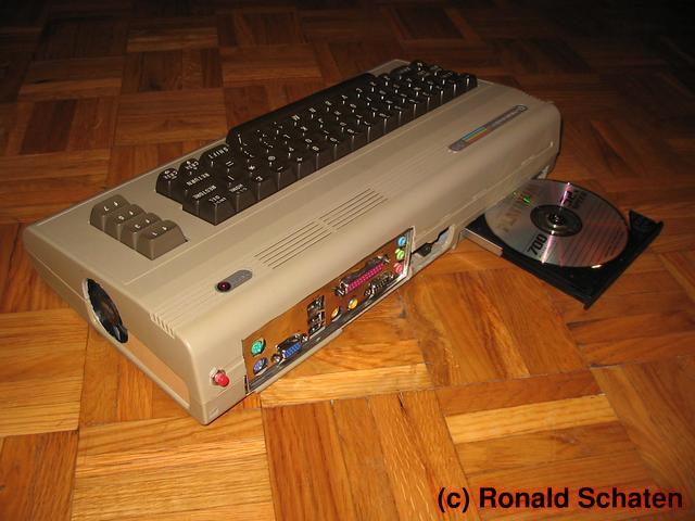
I was given an old Commodore C64 that somebody decided to dispose of. The first version, in germany this case is dubbed ‘Brotkiste’ (bread box). It didn’t turn on anymore, and lacking any personal Commodore history I didn’t hesitate long before taking it apart.
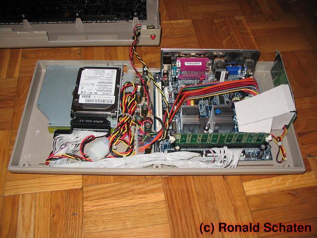
Unfortunately, I didn’t know about microcontrollers at that time, otherwise I would have been able to save the functionality of the keyboard. I wasn’t able to, so parts of the underside of the keyboard had to go, to make space for CPU cooler and RAM.
I inserted a VIA EPIA M10000b, so the C64 ran at 1GHz. The system was completed by 256MB RAM, a 2,5″-20GB-harddisk, a CD-ROM from a notebook and an external power brick.
The C64-PC
Built like this I could attach the unit to my TV set, mainly for playing some games on it. But to be honest: this was one of the projects that made more fun during the build than afterwards…
Nowadays I would build this in a different way. A Raspberry would look great in the case. Needing much less space it would even be possible to keep the keyboard in a working condition. And running the Retropie distribution you could even have this certain 80’s feeling…
 Lieber auf Deutsch?