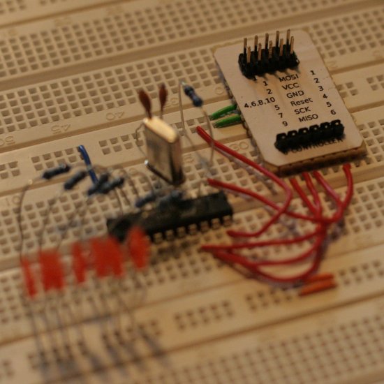
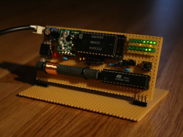
The assembled clock
In Germany, the official time is transmitted in a signal called
DCF-77. You can find many descriptions of the signal format on the internet.
The Binary DCF-77 Clock is a simple device to receive and decode the signal and display the current date and time in binary form. The signal is received in a stock DCF-77 receiver module, decoded with an ATmega8 microcontroller and displayed in binary form on an array of LEDs. This array consists of for lines with eight LEDs each. The ATmega8 is not able to control 32 LEDs at once, so an SAA1064 module is used which is connected via I2C-bus.
The time should be displayed in several different binary formats, the format can be selected with a simple button. The formats will be described later.
The distribution contains the firmware for the controller, the schematics, the documentation and a copy of the GPL license.
Building and installing
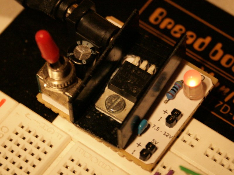
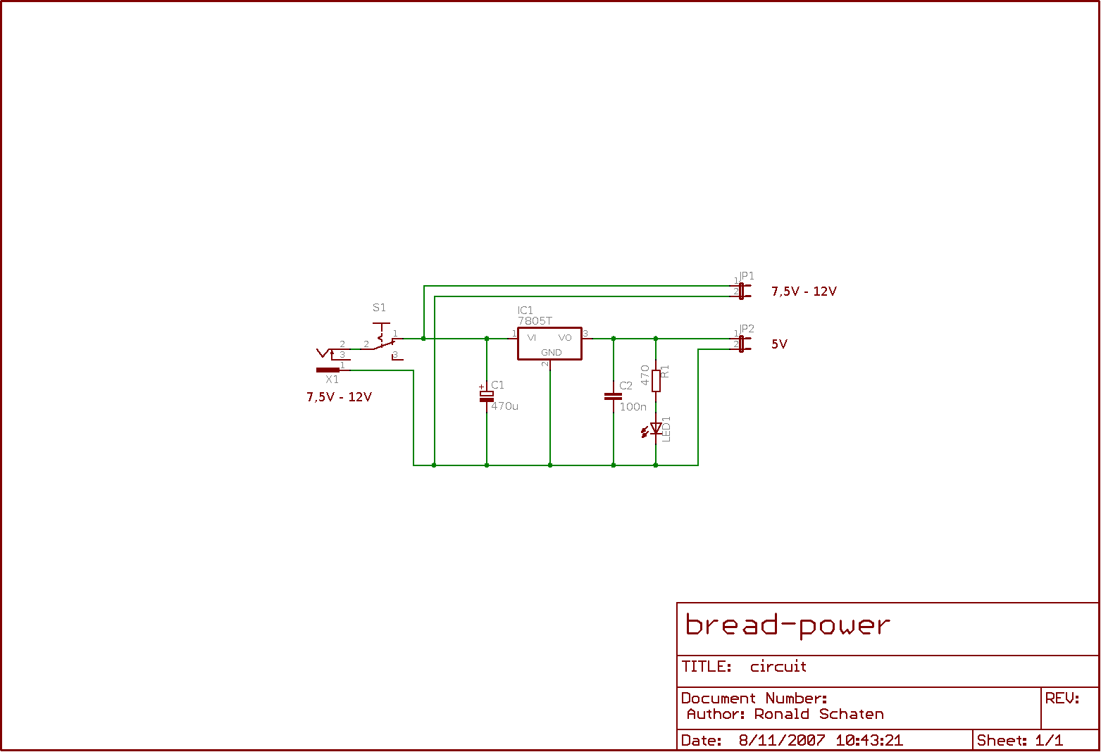
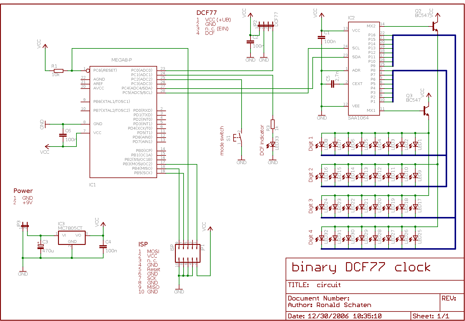
The circuit is not too complicated
The installation is described in the documentation.
Usage
Connect the device to a DC power source with 9V. As long as no time has been decoded, a running light is shown on the output LED array. The single DCF indicator LED should start flashing to indicate that a signal is received. It is set to on when the input signal is high, and switched off if the signal is low. So you should see it flashing with one flash per second, each flash being 100ms or 200ms long.
If the signal is received correctly, after about two minutes the clock should be able to tell the correct time.
Reading the time
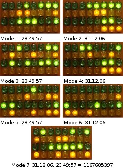
The different modes
The time and date are displayed in seven different styles. You can select the style by pressing the button for a while. A pattern of lights indicate which mode is selected, you can read it as a binary value.
Mode 1: Time as binary
This simply displays the hours, minutes and seconds as bytes, one after each other. The fourth line of the display stays blank.
Mode 2: Date as binary
This is like the previous, with the difference that it displays the day of the month, the month and the year in the first three lines. The last line shows the day of the week, monday being a 1, tuesday a 2 and so on.
Mode 3: Time as BCD
This shows the time as binary coded digits (BCD). The first line displays the hours. The left four LEDs indicate the 10-hours, the right four LEDs indicate the 1-hours.
In the same way, the second and third line display the minutes and the seconds.
Mode 4: Date as BCD
This is like the previous mode, but the date is displayed.
Mode 5: Time as BCD (vertically)
This shows the time in a BCD-form as described in mode 3, but the BCD-values are put vertically next to each other. So in the first two colums you can read the hours, the third column is empty, the fourth and fifth columns show the minutes, the sixth is empty and the seventh and eighths indicate the seconds.
Mode 6: Date as BCD (vertically)
This is like mode 5, but it displays the date.
Mode 7: Unix timestamp
This is probably the least human readable format. It shows a 32-bit value of the seconds since january 1st, 1970. 
Demo mode
If you connect the clock in a place with a poor DCF-reception, but want to demonstrate the functions, you can use the demo mode. To toggle this, you can touch and hold the button for about five seconds. Afterwards, you can switch through the different display modes. The time displayed will stand still, so this can be used to explain the display modes without a hurry.
Switching to demo mode is indicated by all LEDs flashing for a short moment. Leaving demo mode shows an empty rectangle for a short moment.
Drawbacks
I didn’t expect the DCF-signal to be so easily disturbed. In my case sometimes there is no usable signal left when I put my notebook with WLAN next to the clock. Fortunately, the time will be counted further until the next ‘correct minute’ is received.
Thanks!
I’d like to thank Michael Meier, who developed and published a much more sophisticated clock on his site. The SAA1064-stuff and the routine to calculate the Unix timestamp are based on his project. You can find it on his page.
And once again I’d like to give special credits to Thomas Stegemann for help with the C language.
License
This project is licensed under the GNU General Public License (GPL). A copy of the GPL is included in License.txt.
Download