I didn’t have this article on my blog in 2009, it came over from my old CMS in 2015.
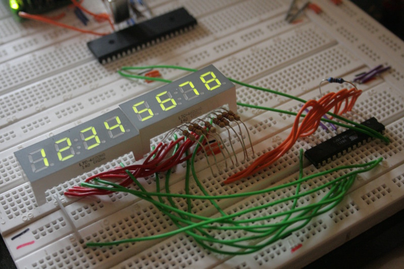
Test circuit on breadboard
Purpose
For my next project, I need to display number values on seven-segment-displays. I bought a bunch of 4-digit-displays a while ago, now I’m going to put them to a use. They are built with four digits in one case, and 12 pins on the underside. Eight of them are the cathodes of the segments (seven segments plus dot), four are the anodes. One for each digit.
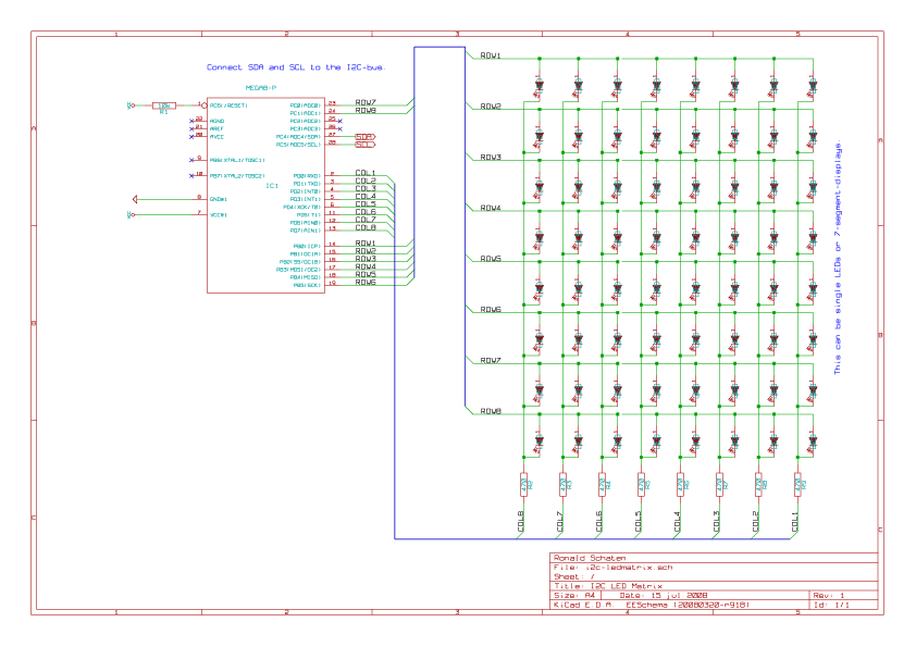
You can imagine these modules as a matrix of four times eight LEDs, as can be seen in the included circuit. I use two of these, so I have a matrix of eight times eight LEDs.
The rows and columns of this matrix are connected to the microcontroller, so it can power them row by row. This has two advantages: at first a maximum of eight LEDs is powered at a time, so power consumption is lowered. And at second you need only 16 pins of the controller to address a total of 64 LEDs.
Driving the LEDs in this way makes them flicker a bit, but the controller is fast enough to keep the flickering way above the level you would be able to recognize.
I could have connected my display modules directly to the main controller of my next project, but I don’t have enough free pins on that. As a further benefit, multiplexing the LEDs on a second controller makes the main program easier to write, since I don’t have to mind the timing. So the solution is to use a cheap ATmega8 as LED driver and use the I2C-bus to tell it what to display.
I2C communication
The ATmega8 has a built-in hardware I2C-interface, so it doesn’t take very much code to use it. Nevertheless, I used a little library that Uwe Grosse-Wortmann (uwegw) published on roboternetz.de. I only reformatted it a bit to make the code resemble my style. It is well commented, but the comments are in german. Since only one global array, one init-function and an interrupt service routine are used, it shouldn’t be too hard for english-speaking people to figure out how it is used.
Usage
On the other end of the communication, I used the excellent Procyon AVRlib written by Pascal Stang. You can find it here.
|
1 2 3 4 5 6 7 8 9 10 11 12 13 14 15 16 |
#define I2C_LEDMATRIX 0x10 // address of the device timerInit(); // initialize timers timerPause(100); // give everything a little time to settle i2cInit(); // initialize i2c function library timerPause(100); // wait a bit more while (1) { // endless loop uint8_t buffer[9]; // prepare buffer // loop until 255 for (uint8_t i = 0; i <= 255; i++) { // set all bytes of the buffer to value i memset(buffer, i, sizeof(buffer)); // send the buffer via I2C-bus i2cMasterSend(I2C_LEDMATRIX, sizeof(buffer), buffer); timerPause(500); // wait, so you have the time to watch } } |
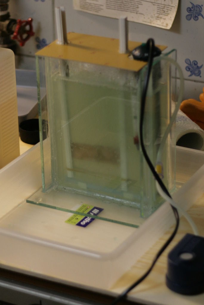
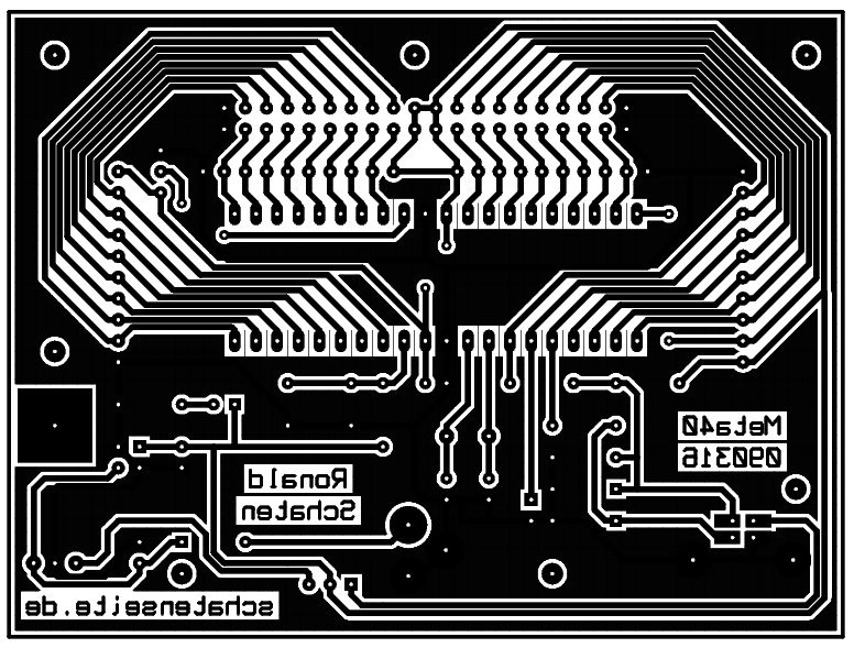
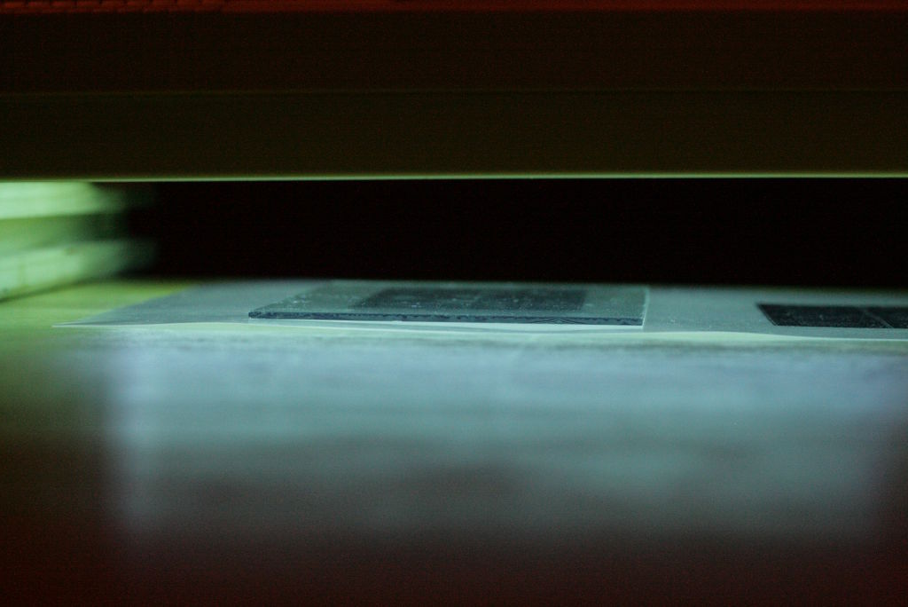
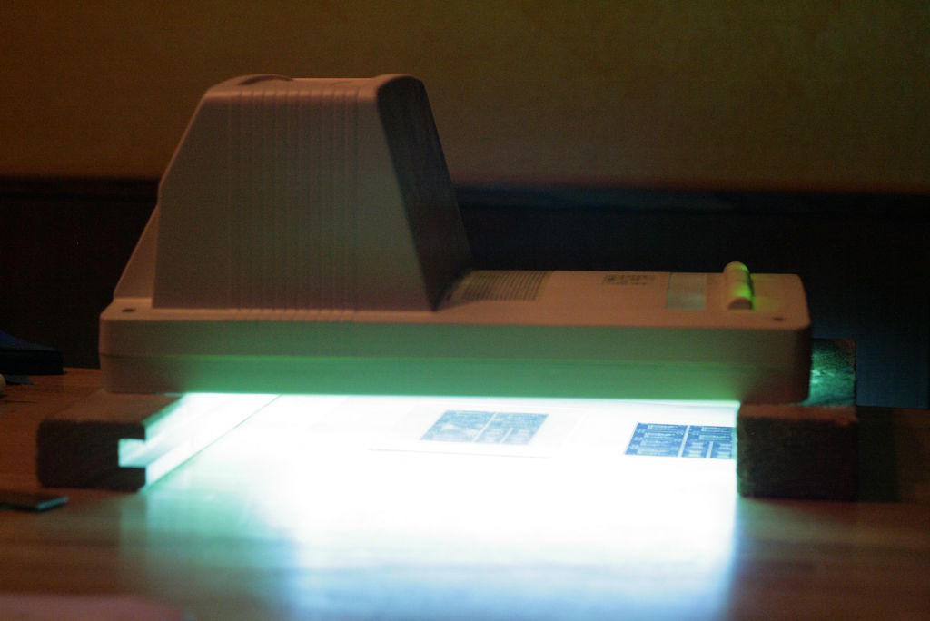
The Circuit
Displaying numbers
If you solder 7segment displays to the unit and intend to display numbers or characters on it, you need to define them on the master-side of the bus. I didn’t include the definitions in this library because I want the master to have the full flexibility of displaying whatever it wants to, even if it are no numbers.
However, if you are going to use 7segment displays, definition of the numbers still depends on how you soldered them to the controller. I don’t know if the pin-outs are commonly standardized.
To give an example of how you would implement this, here is a fragment of code that defines hexadecimal numbers for usage on my displays:
|
1 2 3 4 5 6 7 8 9 10 11 12 13 14 15 16 17 18 19 20 21 22 23 24 25 26 |
// Names of the segments: // aaaaa // f b // f b // ggggg // e c // e c // ddddd h uint8_t characters[16]; // c e g a h f b d characters[ 0] = (1 << 0) | (1 << 1) | (0 << 2) | (1 << 3) | (0 << 4) | (1 << 5) | (1 << 6) | (1 << 7); // 0 characters[ 1] = (1 << 0) | (0 << 1) | (0 << 2) | (0 << 3) | (0 << 4) | (0 << 5) | (1 << 6) | (0 << 7); // 1 characters[ 2] = (0 << 0) | (1 << 1) | (1 << 2) | (1 << 3) | (0 << 4) | (0 << 5) | (1 << 6) | (1 << 7); // 2 characters[ 3] = (1 << 0) | (0 << 1) | (1 << 2) | (1 << 3) | (0 << 4) | (0 << 5) | (1 << 6) | (1 << 7); // 3 characters[ 4] = (1 << 0) | (0 << 1) | (1 << 2) | (0 << 3) | (0 << 4) | (1 << 5) | (1 << 6) | (0 << 7); // 4 characters[ 5] = (1 << 0) | (0 << 1) | (1 << 2) | (1 << 3) | (0 << 4) | (1 << 5) | (0 << 6) | (1 << 7); // 5 characters[ 6] = (1 << 0) | (1 << 1) | (1 << 2) | (1 << 3) | (0 << 4) | (1 << 5) | (0 << 6) | (1 << 7); // 6 characters[ 7] = (1 << 0) | (0 << 1) | (0 << 2) | (1 << 3) | (0 << 4) | (0 << 5) | (1 << 6) | (0 << 7); // 7 characters[ 8] = (1 << 0) | (1 << 1) | (1 << 2) | (1 << 3) | (0 << 4) | (1 << 5) | (1 << 6) | (1 << 7); // 8 characters[ 9] = (1 << 0) | (0 << 1) | (1 << 2) | (1 << 3) | (0 << 4) | (1 << 5) | (1 << 6) | (1 << 7); // 9 characters[10] = (1 << 0) | (1 << 1) | (1 << 2) | (1 << 3) | (0 << 4) | (1 << 5) | (1 << 6) | (0 << 7); // a characters[11] = (1 << 0) | (1 << 1) | (1 << 2) | (0 << 3) | (0 << 4) | (1 << 5) | (0 << 6) | (1 << 7); // b characters[12] = (0 << 0) | (1 << 1) | (0 << 2) | (1 << 3) | (0 << 4) | (1 << 5) | (0 << 6) | (1 << 7); // c characters[13] = (1 << 0) | (1 << 1) | (1 << 2) | (0 << 3) | (0 << 4) | (0 << 5) | (1 << 6) | (1 << 7); // d characters[14] = (0 << 0) | (1 << 1) | (1 << 2) | (1 << 3) | (0 << 4) | (1 << 5) | (0 << 6) | (1 << 7); // e characters[15] = (0 << 0) | (1 << 1) | (1 << 2) | (1 << 3) | (0 << 4) | (1 << 5) | (0 << 6) | (0 << 7); // f |
Drawbacks
Till now, the device worked in all situations I tested it in. So far everything is fine.
Thanks!
I’d like to thank the authors of the libraries I used: Uwe Grosse-Wortmann (uwegw) for the I2C-slave and Pascal Stang for the Procyon AVRlib.
About the license
My work is licensed under the GNU General Public License (GPL). A copy of the GPL is included in License.txt.
Download
- i2c-ledmatrix_090506.tar.gz – Source code and documentation, 212kB