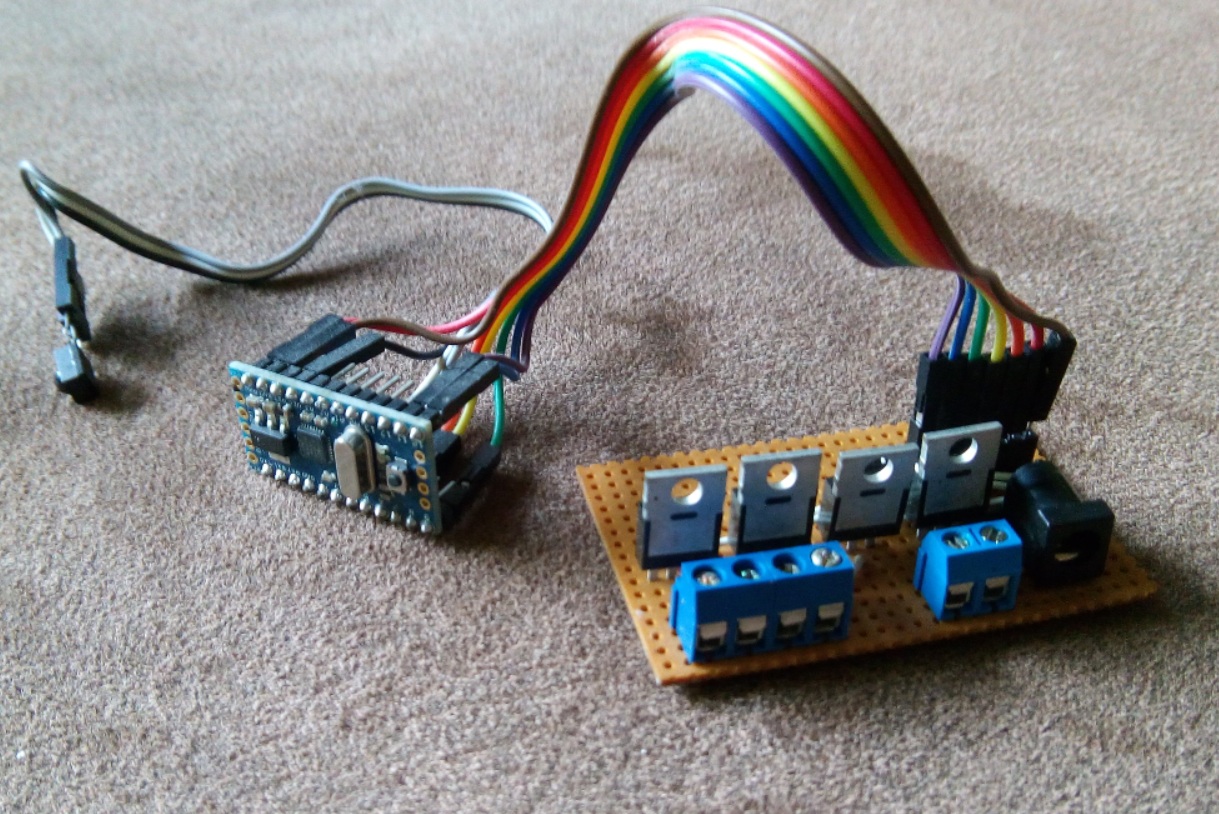
The circuit as it ran for two years
In early 2014, we renovated our living room. One wall got a rocky structure, and I thought that was the perfect place for a grazing light from above. This screamed for LED-strips. Fooling around with my daughters, I mentioned a plan of installing a pink light. The plan was to go with warm-white, but they insisted on a pink light… two against one, I was in defense position. 
Theoretically, a simple RGB-strip can be made to give white light. Practically, most times that’s a really ugly tone of white. So I installed a warm-white strip next to the RGB one. The controller that was delivered with the RGB-strip wasn’t able to power this combination, so I needed a RGBW controller. I couldn’t find an affordable one, so I had to build it myself.
That’s how it works
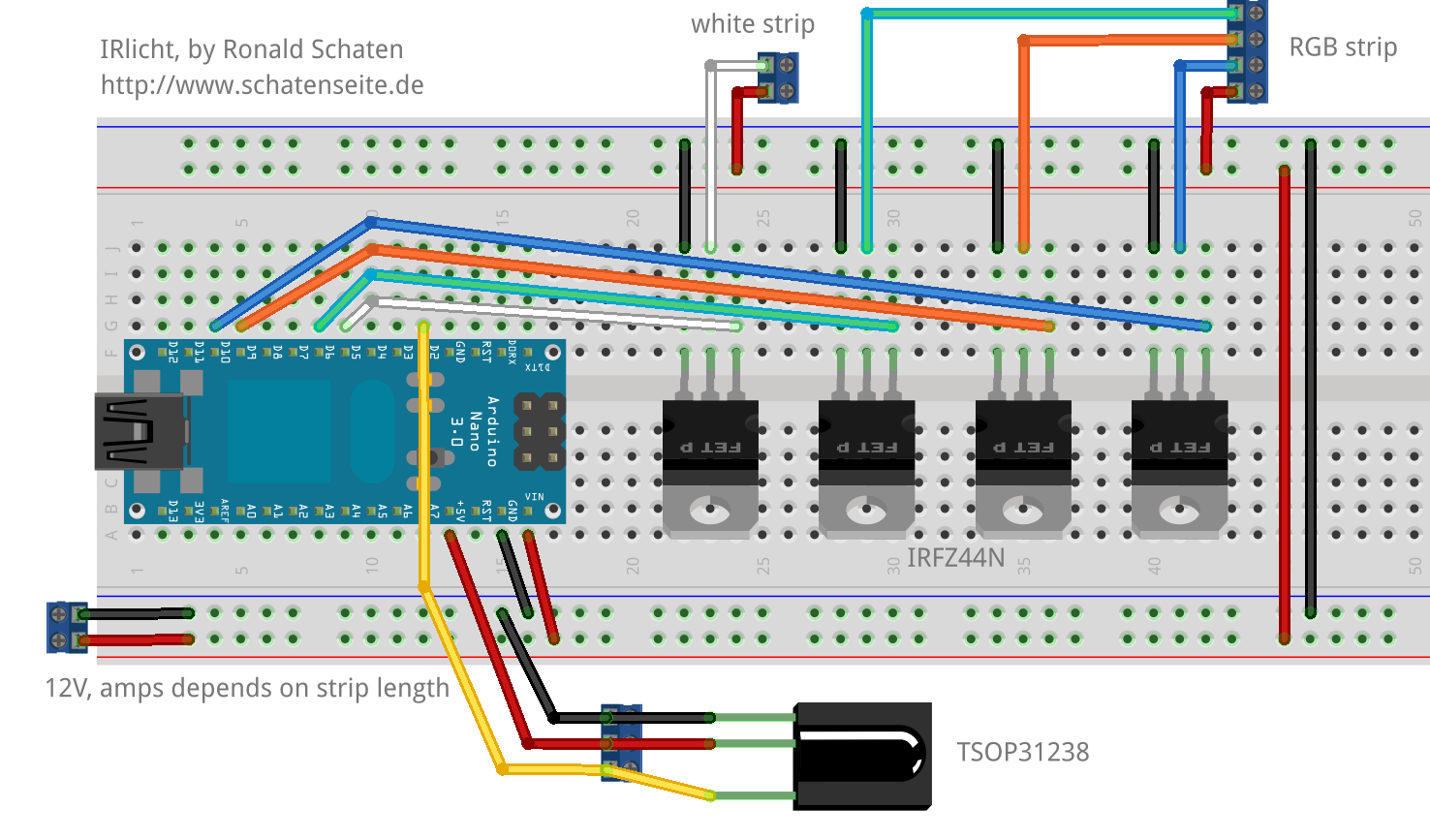
The second prototype I built using MOSFETs, to test how I would be able to control the LED-strips with an Arduino. They are powered with 12V, after all.
The final build is pictured on the photo above: an Arduino Pro Mini (the one without USB interface), and a simple PCB that is wired for controlling the strips. There’s an infrared receiver wired to the Arduino. Initially, that was a TSOP31238, but I fried it just before finishing the project by wiring it wrong. Wanting to get this done, I gutted an old DVD player. I don’t have the slightest idea what type of receiver this is, but it works. 
That means: it did work. Almost exactly for two years. Till today. Now it’s obsolete — as I said. Sources and documentation go by the name of IRlicht, I published today.
Oh, and if that’s of anybodys concern: until today, the lamp was used almost only in the white mode. The colors — and especially the color changing modes — were used only for testing and for showing how it works. It was used rarely enough that I had to look up the used keys in the source code…